Find Articles by Series: List View for Drafting
Designing, installing and balancing hydronic system became infinitely easier with the introduction of a handy little gadget called a pressure independent control valve or “PIC” valve. These valves, which first hit the market nearly two decades ago, have revolutionized hydronic balancing....
Throughout our Hydronic Balancing Series, we’ve been slowly and meticulously making our way to the more complex control systems that we see today. We walked you through the steps of proportionate balancing a simple 3-zone system and taught you how to trim an impeller in accordance with ASHRAE 90.1. Today, we’re going to see what happens when we add variable speed drives to the system.
If you’ve read Parts 1 thru 9 in this Hydronic Balancing Series then you should have a solid understanding of the fundamentals of balancing. If not – go back and review the previous blogs. You need these fundamentals to understand what we will discuss here in Part 10, which is...
In our last blog we covered (in detail!) the step-by-step process of proportionately balancing a hydronic system. But many of you may be wondering if all that legwork is truly necessary when theoretically....
The task of proportional balancing is the first step to achieving an energy efficient pumping system. It involves adjusting the system balancing valves to make certain that all zones get proportionate flow under design conditions. Once this task is complete, it gives us the opportunity to trim the fat out of the system for greater efficiency...
Balancing isn’t just about adjusting valves. Sometimes (very often in fact) it is about evaluating the performance of the pump(s) under real world operating conditions. Remember what ASHRAE 90.1 has to say about Hydronic System Balancing: “Hydronic systems shall be proportionately balanced in a manner to first minimizethrottling losses; then the pump impeller shall be trimmed or pump speed shall be adjusted to meet...
Balancing contractors and facility operators would have a much easier time balancing a hydronic system if they were present during the system design process. Unfortunately that is rarely the case so there is usually a certain amount of detective work that comes with balancing. The biggest part of that is getting a handle on the overall pumping system. You can’t effectively balance a system without understanding...
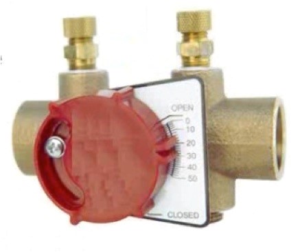
There are multiple choices for creating a balanced hydronic system. Here is a list of the most commonly used devices.
What is a system curve and how is it used to develop a balanced hydronic system?
The “system curve” is a graphical representation of the head losses and gains of a particular piping system that result from changes in flow. And it’s all based on this law:
As you double the flow through the piping the pressure drop increases by the square. In other words, the pressure drop increases by four times what it was.
By Chris Edmondson
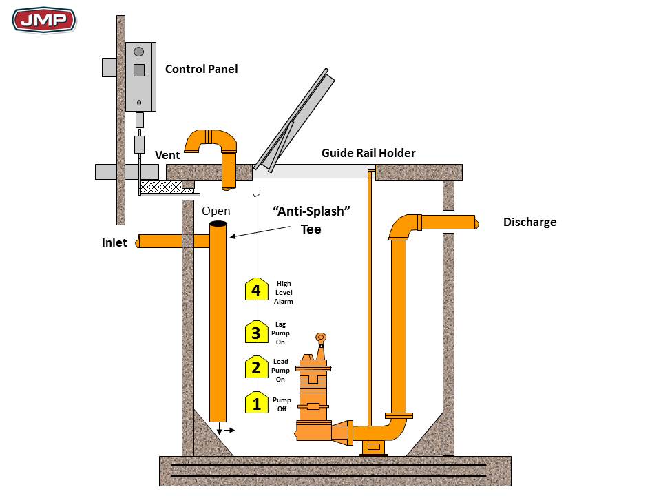
Over the last several weeks we’ve talked about many aspects of designing a commercial sewage lift station, from flow rates to components. In this blog, we’re going to work through a really simple sizing example. Let’s say we are sizing a sewage station for a retirement facility made up of primarily independent living units.
By Chris Edmondson
Just in case you haven’t gotten the message in this series on designing a commercial sewage lift stations, the design process involves a lot more than selecting a sewage pump or sump pump. The most reliable sewage lift
Pumps used in commercial sewage lift stations come in a variety of types (effluents, grinders, etc.) To determine which type is right for your application you must answer two questions:
- What size solids will have to be pumped?
- What is the size of the discharge pipe?
By Chris Edmondson
In a previous blog we discussed how to determine the flow for a commercial sewage lift station so you determine the necessary pump capacity. Today we are going to discuss Total Dynamic Head, which is also critical to sizing a pump for a sewage lift station. Not only is it absolutely necessary to select a
By Chris Edmondson
Section 712 of the International Plumbing Code (IPC), Section 712, places a burden on the shoulders of engineers. You have to design the sewage pit or basin that collects the sewage and houses the pump(s). To do that properly, you need to address the following questions:
How big should the basin be? According to Section 712.3.2, “The sump pit shall be no less than 18
By Chris Edmondson
Sometimes codes just aren’t very helpful. Take Section 712.4.2 of the International Plumbing Code (IPC) and its insight into the selecting flow capacity for a sewage and ejector pumps:
712.4.2 Capacity. A sewage pump or sewage ejector shall have the capacity and head for the application requirements.
(Thanks, IPC….)
Clearly, having the proper flow is necessary to efficiently discharge wastewater from a commercial plumbing system – but how do you determine the flow rate for the sewage system so you can properly size the pump?
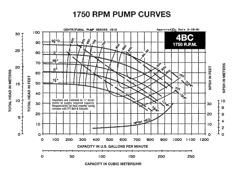
If a picture is worth a thousand words then a pump curve must be worth several thousand.
Make no mistake, there’s a lot of information on a centrifugal pump curve like the one shown here. It’s no wonder that many newly practicing engineers are a little intimated by them.
**NOTE: You'll see below that Part 4 was duplicated. Please take a look and see if you can discern any differences. Once checked, we'll peek at the URLs and delete the one that needs to go.
By Chris Edmondson
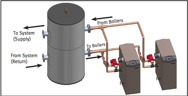
There’s more than one way to pump a chiller or boiler system. In fact, there are five common approaches, and all but one includes some variation of our topic of late -- primary secondary pumping.
Variable Primary Pumping
Contemporary systems that do not utilize primary secondary pumping are typically known as variable primary systems. In this simple design, there is only one set of pumps (chiller or boiler pumps) creating flow for the entire system.
By Chris Edmondson
Piping in a primary secondary pumping systems as a whole can be quite complex, but when it comes to the “primary” part of the system, there are really only two approaches: Dedicated or Non-dedicated.
Figure 1 shows the chillers in a primary secondary system piped with one pump per chiller. If the chillers
By Chris Edmondson
Now that we know what happens when we vary flows and mix temperatures in a primary secondary pumping system, let’s explore these theories in some more realistic scenarios.
As discussed in a previous blogs, when it comes to primary secondary systems, one of three flow patterns is always in occurrence:
By Chris Edmondson
Low Delta T Syndrome. The terminology alone strikes fear in the hearts of anyone involved in chiller plant design or operation. We know Low Delta T Syndrome is bad. We know it wastes energy. The very topic has given rise to countless technical articles and white papers that most of us haven’t the time or patience read. But take heart because believe it or not, if you’ve read and understand Part 1 and Part 2 of this Series, you already have the building blocks to understand Low Delta T Syndrome. You just don’t know it yet.
By Chris Edmondson
What happens in a pipe when water of two different temperatures (and perhaps different flow rates) merge?
There’s a pretty straightforward formula that tells you exactly what the resultant water temperature will be. In this blog, we’ll go over that calculation, as well as take a closer look at how blended temperatures
Are you involved in the design or installation of hydronic systems? Do you anticipate becoming involved?
If you answered yes to either of these questions, this blog series on primary/secondary pumping will interest you. If you are a hydronic’s veteran, feel free to skip the first few blogs in the series – they may be too much of a review. Better yet, pass them onto a junior associate and

















What are your options when unbalanced circuits in an existing hydronic system are creating comfort issues due to underflow or overflow through coils? We just spent the last twelve blogs describing the various methods for balancing a start-up system but do those same methods apply to existing systems and retrofits?
The short answer is....