Hydronic Balancing Series
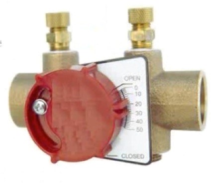
Designing, installing and balancing hydronic system became infinitely easier with the introduction of a handy little gadget called a pressure independent control valve or “PIC” valve. These valves, which first hit the market nearly two decades ago, have revolutionized hydronic balancing....
Throughout our Hydronic Balancing Series, we’ve been slowly and meticulously making our way to the more complex control systems that we see today. We walked you through the steps of proportionate balancing a simple 3-zone system and taught you how to trim an impeller in accordance with ASHRAE 90.1. Today, we’re going to see what happens when we add variable speed drives to the system.
If you’ve read Parts 1 thru 9 in this Hydronic Balancing Series then you should have a solid understanding of the fundamentals of balancing. If not – go back and review the previous blogs. You need these fundamentals to understand what we will discuss here in Part 10, which is...
In our last blog we covered (in detail!) the step-by-step process of proportionately balancing a hydronic system. But many of you may be wondering if all that legwork is truly necessary when theoretically....
The task of proportional balancing is the first step to achieving an energy efficient pumping system. It involves adjusting the system balancing valves to make certain that all zones get proportionate flow under design conditions. Once this task is complete, it gives us the opportunity to trim the fat out of the system for greater efficiency...
Balancing isn’t just about adjusting valves. Sometimes (very often in fact) it is about evaluating the performance of the pump(s) under real world operating conditions. Remember what ASHRAE 90.1 has to say about Hydronic System Balancing: “Hydronic systems shall be proportionately balanced in a manner to first minimizethrottling losses; then the pump impeller shall be trimmed or pump speed shall be adjusted to meet...
Balancing contractors and facility operators would have a much easier time balancing a hydronic system if they were present during the system design process. Unfortunately that is rarely the case so there is usually a certain amount of detective work that comes with balancing. The biggest part of that is getting a handle on the overall pumping system. You can’t effectively balance a system without understanding...
There are multiple choices for creating a balanced hydronic system. Here is a list of the most commonly used devices.
What is a system curve and how is it used to develop a balanced hydronic system?
The “system curve” is a graphical representation of the head losses and gains of a particular piping system that result from changes in flow. And it’s all based on this law:
As you double the flow through the piping the pressure drop increases by the square. In other words, the pressure drop increases by four times what it was.


What are your options when unbalanced circuits in an existing hydronic system are creating comfort issues due to underflow or overflow through coils? We just spent the last twelve blogs describing the various methods for balancing a start-up system but do those same methods apply to existing systems and retrofits?
The short answer is....