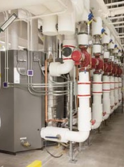
Condensing Boiler Plant Piping Design & Control Part 2: Variable Primary Flow Systems
/By Chad Edmondson
We now learn, work, and heal in buildings that are increasingly heated using a combination of two energy efficient technologies -- condensing boilers and variable flow. Contrary to the previously held beliefs that all boilers require constant flow, today’s full condensing boilers can and should be designed for variable flow. Unlike non-condensing boilers, these condensing boilers are not susceptible to thermal shock, so there is no need for mixing valves, mandatory primary-secondary piping, or high return water temperatures. But it is necessary to design these systems to keep both boilers and pumps operating within their proper ranges.
There are basically two ways to incorporate variable flow into a condensing boiler system. You can have just one set of primary pumps, which vary flow through the entire system from boilers to coils, or you can have both primary and secondary pumps, which vary flow through their respective loops. In this blog, we’ll address the former -- condensing boiler systems that are designed with just one set of variable primary flow pumps. This is known as a variable primary flow (VPF) system.
Figure 1
Clearing A Flow Path
Figure 1 shows the basic piping layout of a VPF system. This piping arrangements not only assures that proper operation, but it will also help owners meet the criteria of ASHRAE 90.1-2010 and 2013 which says that when a boiler plant includes more than one boiler, provisions shall be made so that the flow in the boiler plant can be automatically reduced, correspondingly, when a boiler is shut down.To do this you must include the following control devices in the boiler supply and return lines:
Flow limiters for each boiler. These devices, installed right before the inlet to each boiler in the system, prevent any over-pumping of the boiler. It is fine to vary flow through full condensing boilers, but every manufacturer has their own set of specifications for minimum and maximum flows through the boiler which should be observed so has not to harm the equipment. These flow limits will override any variance in flow for the sake of efficiency.
2-Way isolation valves for each boiler. These valves are necessary to stop flow through the boiler when it is not running, and thus allow you to meet the afore mentioned ASHRAE standard which has been adopted into the current Energy Code. These valves must be timed to open and closed based on the boiler volume and also the boiler control response time. The manufacturer can provide this information.
The valves must also be interlocked with the pumps so the latter is never running unless at least one boiler isolation valve is open. Otherwise you will deadhead the pump. The pumps need to run for a time after boiler shut-off in order to remove the residual heat from the boilers, therefore the valve must remain open for a short period even after the boiler stops running. Again, the length of time this process takes depends on the boiler itself.
Variable flow controls must be configured to:
Establish the minimum flow rate for each boiler at start-up per the manufacturer’s specifications.
Operate the pumps based on the minimum system volume required for boiler start-up and staging. Otherwise the system will short-cycle or hit high limit.
Maintain a pump minimum flow rate based on the pump manufacturer’s recommendation.
Finally, 3-way valve(s) should be installed at the end of the system (Figure 2). These valves are necessary to establish the minimum flow through the boiler or the pumps (whichever has the larger minimum value). The valve maintains a pathway for the water to flow back to the boiler(s) when the coils are not operating and their own 2-way valves are closed. Remember, a certain amount of flow is also necessary prior to boiler start-up and following boiler shutdown so that all the minimum flow requirements are met during these brief periods.
Figure 2
For more information watch this video:


