

Steam Heating Systems Part 6: Pilot-Operated Steam PRVs in Parallel
/By Mark Bingham
Steam systems require precise pressure control to ensure efficiency, safety, and equipment longevity. Pilot-operated pressure reducing valves (PRVs) are widely used for their accuracy and stability under varying loads. When loads exceed the capacity of a single PRV and/or load variability is high, these valves are often installed in parallel. This arrangement is usually referred to as a 1/3 – 2/3 parallel valve station, though the 1/3 and 2/3 are somewhat arbitrary, as the valves may be selected at other fractions of the total flow.
Parallel PRVs offer staging capability and redundancy. At reduced loads, one of the valves (usually the smaller one) handles the required flow. This prevents valves from operating at a slightly open position, reducing wear on the valve plug and seat and improving pressure control. If one PRV fails or requires maintenance, the other may be able to maintain the steam supply for part-load operation. Manually controlled parallel bypass valves are sometimes included and can be opened to supplement the flow of a single valve if one is offline.
Pressure Settings
Proper pressure settings are essential to avoid excessive valve wear and poor pressure control. The smaller parallel valve should be set at the desired downstream pressure (e.g., 100 psig). The larger valve should be set slightly lower (typically 2–5 psi below the primary) so that it only opens when the smaller valve is fully open and can’t meet the total demand.
Parallel valves should never be set at the same pressure. Operating both valves slightly open results in high steam velocities that cause seat and disc erosion, a condition sometimes referred to as wire drawing of the seat.
PRV and Safety Relief Capacity
Safety relief valves are required downstream of PRVs to protect against overpressure if a PRV fails. These valves are installed on the low-pressure side of the PRV. At a minimum, the safety relief valve should be selected to handle the full capacity of the largest upstream valve. In some cases, the relief valve is selected to handle the sum of the maximum capacity of all upstream valves. The safety relief valve is typically set at 10% above the reduced pressure setting, but below the lowest maximum working pressure of any downstream piping and equipment.
When determining the required capacity for safety relief valves, PRV capacities should be evaluated with the largest possible seat. A reduced-port valve may be installed, but the seat could be changed to a full-port valve in the future, significantly increasing the valve's maximum capacity.
PRVs must discharge through a short nipple into a drip pan elbow so that condensate that forms in the discharge piping drains after the valve opens. The outlet of the drip pan elbow is larger than the valve discharge and must be piped with a continuous upward slope (preferably vertical) to a safe location outside the building.
Best Practices
The following best practices will help ensure optimal performance and longevity of your parallel steam PRV installation.
• Include upstream and downstream isolation valves (typically gate valves) for each PRV to facilitate maintenance.
• Install strainers after the upstream isolation valve to protect the PRV and pilot. The strainers should be installed in the horizontal plane to minimize condensate accumulation.
• Install pressure gauges upstream and downstream for monitoring. Compound pressure gauges should be used because a vacuum is likely to occur when the steam system is shut down.
• Install an upstream drip trap with isolation valves to prevent entrained condensate droplets from damaging the PRVs and pilots.
• Install a downstream drip trap with isolation valves to prevent condensate from being transported with the reduced-pressure steam.
• Select piping based on steam velocities to minimize noise. Some facilities have specified maximum velocities.
• The high-pressure piping will often be larger than the valve inlet. Install eccentric reducers flat-on-bottom to prevent condensate accumulation.
• Low-pressure piping is usually larger than high-pressure piping. Reducers on the PRV outlet may be concentric or eccentric. Sometimes installing eccentric reducers flat-on-top helps with the pilot piping slope.
• If a manual bypass valve is indicated, it is usually a globe valve selected with a Cv similar to that of the largest PRV. Since this valve is not frequently used, the inlet and outlet piping can be the same size as the valve.
Typical Parallel PRV Installation
Figure 1 illustrates two pilot-operated PRVs in parallel with a manual bypass and a downstream relief valve:
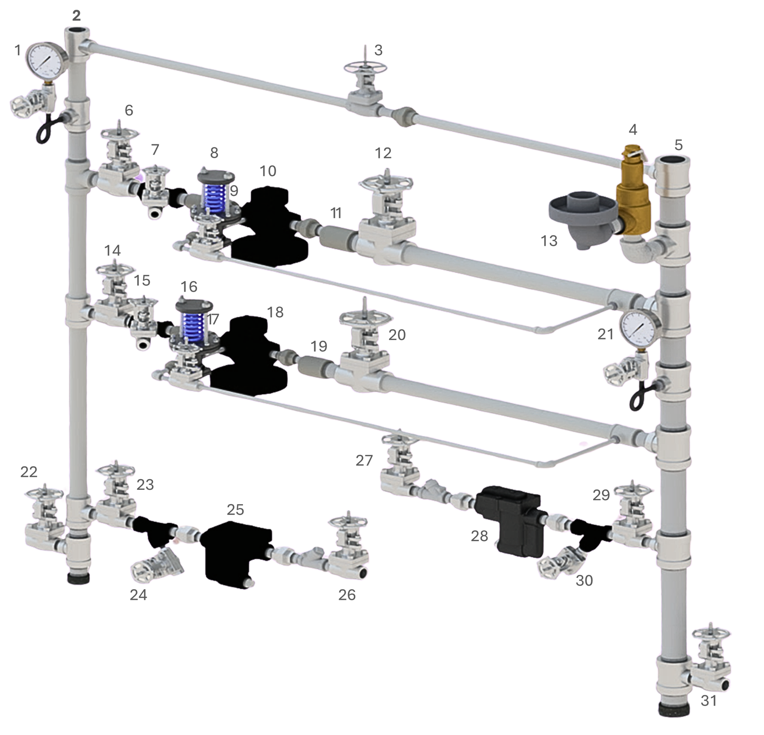
Figure 1: A small parallel PRV system
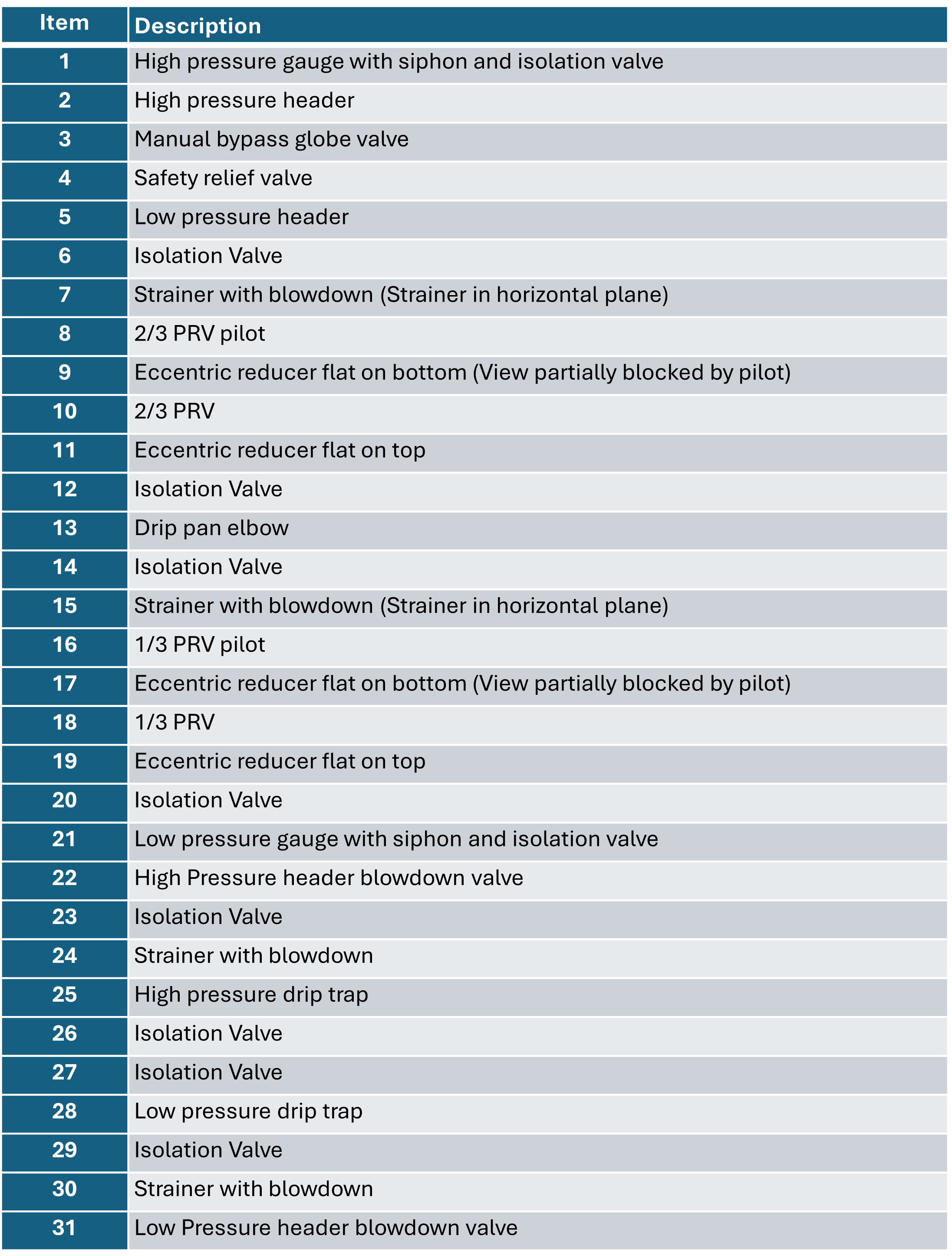
Numbered components in Figured 1 are identified below:
In our next blog, we’ll discuss using pilot-operated steam PRVs in series.
