Steam Heating Systems Part 7: Pilot-Operated Steam PRVs in Series
/By Mark Bingham
In our last blog post, we discussed pilot-operated steam PRVs in series. In this post, we’ll look at PRVs in series as an effective solution for systems that require multiple operating pressures or large pressure reductions. This article explains when and how to install PRVs in series, along with considerations for capacity, pressure settings, and system stability.
Why Use PRVs in Series?
Typically, series configurations are used when a single PRV cannot handle the full pressure drop without excessive wear or instability. Hoffman recommends a maximum pressure drop of 100 psi across a single valve. Pressure drops of up to 150 psi can be accommodated but tend to accelerate valve wear.
Steam systems that require an intermediate pressure between the main header and the final low-pressure line are another common reason for installing PRVs in series.
There are also operational advantages. Splitting the pressure drop between two PRVs improves control accuracy because each valve operates over a smaller pressure range. Lower velocity across each valve minimizes erosion and noise.
Configuration and Capacity
Steam PRVs in series usually include two valves. The first (high-pressure) PRV reduces pressure from the main header to an intermediate level. This valve is set slightly above the required intermediate pressure to ensure stability. The second PRV should be set at the final required pressure. It’s best to maintain a minimum differential (typically 10- 5 psi) between the first and second valve to prevent hunting.
The high-pressure valve must be sized to handle full upstream flow since all steam passes through it. The low-pressure valve may handle the same flow, or if steam is consumed at the intermediate pressure, it may be selected for the reduced load at the low pressure.
Use manufacturer selection software for each PRV. Select valves to keep the noise below 85dB at 3 feet from the valves.
Design Guidelines
Include upstream and downstream isolation valves (typically gate valves) for each PRV to facilitate maintenance.
Install strainers after the upstream isolation valve to protect the PRVs and pilots. The strainers should be installed in the horizontal plane to minimize condensate accumulation.
Install pressure gauges at the high-, intermediate-, and low-pressure headers for monitoring. Compound pressure gauges should be used since a vacuum is likely to occur when the steam system shuts down.
Install a drip trap upstream of each PRV with isolation valves to prevent condensate from impinging on the PRVs and pilots.
Install a drip trap with isolation valves on the low-pressure header to prevent condensate from being carried with the reduced-pressure steam.
Select piping based on steam velocities to minimize noise. Some facilities have specified maximum velocities. The high-pressure piping will often be larger than the valve inlet. Eccentric reducers must be installed flat on the bottom to prevent condensate accumulation.
Reduced-pressure piping will usually be larger than high-pressure piping. Reducers on the PRV outlet may be concentric or eccentric. The installation of eccentric reducers flat on top helps with the pilot piping slope.
If a manual bypass valve is indicated, it is usually a globe valve selected with a Cv similar to that of the PRV. Since this valve is infrequently, the inlet and outlet piping can be the same size as the valve.
Typical Series PRV installation
The following drawing illustrates two pilot-operated PRVs in series, each with a manual bypass, and relief valves on the intermediate and low-pressure headers:
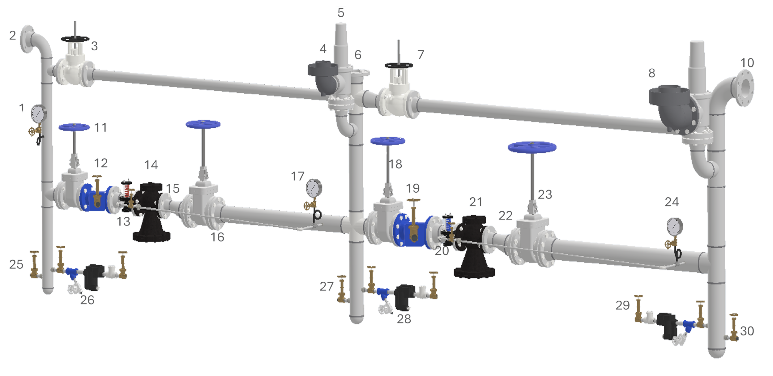
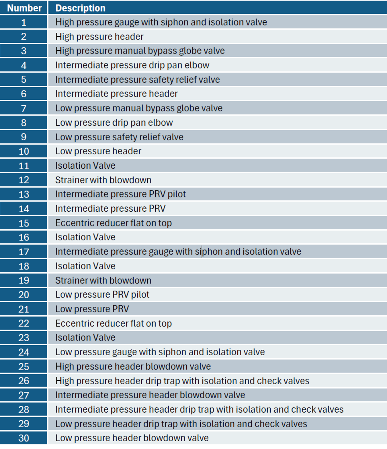
two Pilot operated steam PRVs in series. Numbered components identified below: