Fire Pumps for Sprinkler Systems Part 4: Annual Testing Requirements
/
By Wade Laughon
Fire pumps are a critical part of commercial and industrial fire protection systems. These pumps undergo Acceptance Testing (NFPA 20) upon start-up, but they must also undergo Routine Annual Testing (NFPA 25) at full flow to verify that the pump still meets its original performance within the relevant tolerances.
During annual fire pump testing, technicians must confirm that the pump can deliver the required flow and pressure under field conditions that reflect the installed system. That verification is especially important because some fire pumps can discharge up to 5,000 gpm, and even small errors in test setup, instrumentation, or discharge arrangement can affect the accuracy of the results and the interpretation of the pump curve.
Test Setup and Components
Fire pump test headers
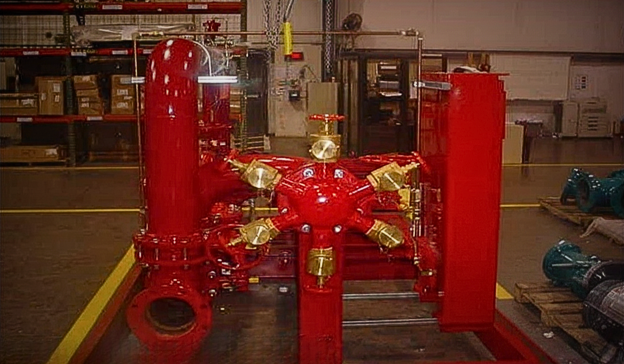
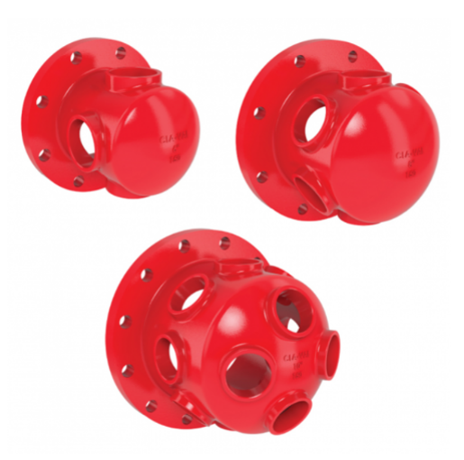
One of the most important components in this process is the fire pump test header. These multi-hose connections allow technicians to discharge water from the pump in a controlled manner without involving the facility’s fire protection system, such as the sprinkler system. From a technical standpoint, the test header helps establish a repeatable flow path for measuring performance and avoids the inaccuracies that can occur when other outlets are used on complex fire water distribution systems. When hydrants on industrial systems also serve process water or draw from multiple sources, the measured flow may not accurately represent the pump being tested, which is one reason a dedicated pump test header is often the preferred arrangement.
NFPA 20 requires the pump installation to be proven by a flow test at 150% of the pump’s rated capacity, or if the water supply cannot support 150% without dropping below the approved minimum suction pressure, then at the maximum achievable flow (but at least 100% of rated flow or the full system demand). That means the test setup has to do more than simply move water—it must support meaningful measurement. The number and size of hose valves used for pump testing must be selected in accordance with the standard, and the hose valves themselves must be listed.
NFPA 20 does permit using wall hydrants, yard hydrants, or standpipe outlets for the pump flow test if they are available in sufficient number/size, but in practice the discharge arrangement must replicate the required test conditions to ensure valid results.”
Installation details play a major role in obtaining valid test data. NFPA 20 requires that the pipe feeding the test header be equipped with a listed butterfly or gate valve near the pump (for isolation), and a drain valve or automatic ball drip at a low point between that valve and the header, to fully drain the header piping after testing.
Pipe Sizing
Pipe sizing is equally important. If the run to the header exceeds 15 feet, or if the piping includes multiple direction changes and associated friction losses, the system may require the next larger pipe size or sizing by hydraulic calculation. Those calculations must reflect the actual test configuration and account for required pitot pressure, hose friction loss, equivalent lengths for fittings and valves, and elevation loss from the pump discharge flange to the outlets.
A typical test header has multiple 2½-inch hose outlets that allow the pump’s high flow (often several hundred or thousands of GPM) to be split into manageable streams and safely directed. Each outlet is connected to a hose discharging to a safe area.
In practice, fire pump testing is not just a discharge exercise—it is a controlled hydraulic verification of the installed fire pump system.
Wade Laughon has 39 years of experience in fire pump sales and applications. He started the fire pump division at JMP when he came to work for the company in 1989.