

A Quick Look at Smart Pump Curves
/By Mark Bingham
In our previous blog series on pump motor efficiency, we discussed the evolution of pump motor efficiency and how this evolution led to the introduction of smart pumps with integrated controls. We also learned that smart pump impellers are not trimmed; instead, they are “optimized” with the largest impeller for the specific horsepower and speed range of the motor. These differences between smart pumps and conventional pumps impact certain parts of their curves. In this blog post, we will review the elements of a smart pump curve, using Xylem’s B&G e-1510X-3BD as our example.
Performance Range
Looking at Figures 1, 2, 3, and 4, you may notice immediately that the performance characteristics of the e-1510X-3BD smart pump are spread across four different curves instead of consolidated into one. This is because of the dynamic performance of a smart pump with integrated variable speed control.

figure 1
Figure 1 contains the head and flow characteristics of the e-1510X-3BD at different speeds. The key elements are:
Model Information. Pump model and motor information. Note that two motor voltage ranges are shown. This pump is available with a motor for either range, but the voltage cannot be changed in the field.
Maximum Speed Curve. The maximum operating speed of the pump. Note that the speed decreases to prevent overloading as the power approaches the motor nameplate horsepower.
Minimum Continuous Stable Flow. The minimum recommended flow rate of the pump.
Maximum Flow Curve. The maximum recommended flow rate of the pump.
Minimum Speed Curve. The minimum operating speed of the pump for continuous operation.
Speed Tags. These notations reflect the motor speed of a given performance curve.
This pump may operate anywhere within the yellow area bounded by the maximum speed curve, the maximum flow curve, the minimum speed curve, and the minimum continuous stable flow curve. However, sustained operation near the minimum continuous stable flow or the maximum flow curve should be avoided! Radial loads increase as the pump approaches the minimum flow curve, and unstable operation will occur if the maximum flow curve is exceeded. Efficiencies also fall significantly when operating at either of these extremes.
Pump efficiency will vary throughout the permissible operating region as flow and head vary. Figure 4, explained below, shows more detailed information about the e-1510X-3BD’s efficiency.
An e-1510X 3BD pump with a full diameter (9.5-inch) impeller is mechanically equivalent to a legacy e1510 with the same diameter impeller. However, the smart pump version is designed to operate over a wider range of speeds, resulting in a larger hydraulic condition coverage.
Required Net Positive Suction Head
Figure 2 is the NPSH curve, which indicates the net positive suction head required of the e-1510X-3BD pump. The dashed NPSH curve corresponds to the maximum speed condition. Subsequent NPSH curves represent the NPSH required at decreasing speeds.
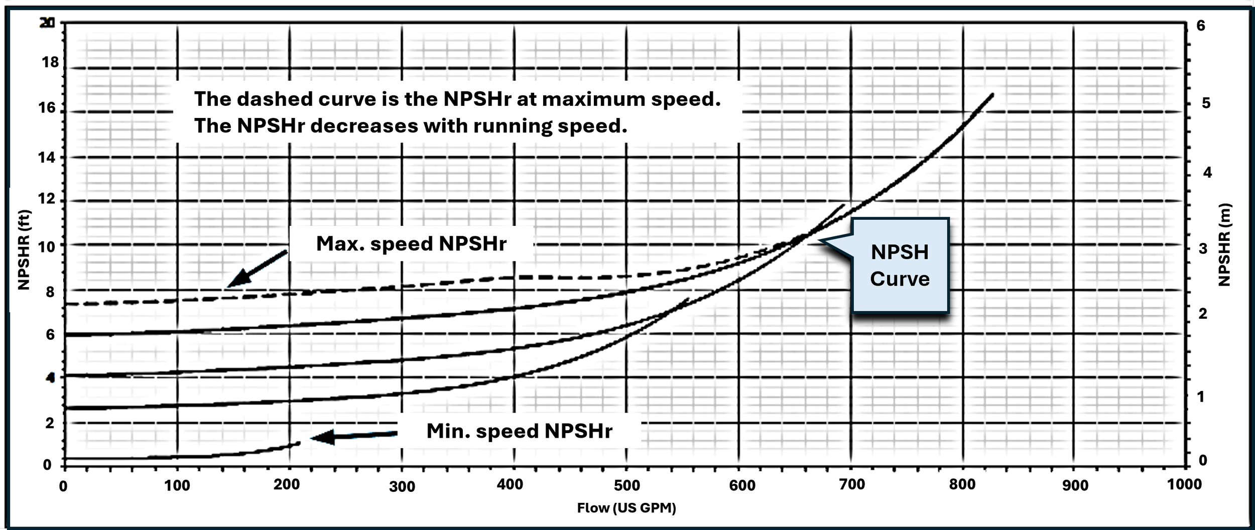
figure 2
Horsepower Curve
Figure 3 is the horsepower curve for the e-1510X-3BD. This curve indicates the input power required to drive the motor (including the smart controller) at a given speed. Note that the horsepower curve levels off at maximum speed, around 420 GPM. This corresponds to the speed reduction to prevent overloading.

figure 3
Pump Efficiency Curve
Figure 4 is the pump efficiency curve with various lines representing (1) just the pump efficiency operating at 100% speed (1800 rpm for the-1510X-3BD), and (2) the efficiency of the pump, motor, and drive per speed. The other curves shown in Figure 4 represent the overall efficiency at different speeds.

figure 4
No Trimmed Impellers!
It is important to note that a smart pump is designed to operate in its specified curve area by varying its speed. Impellers should not be trimmed since the manufacturer has selected the optimum impeller diameter for the smart pump’s motor. The integrated drive and controller will be factory set to operate at the specified service conditions.
Table 1 lists a few arbitrarily chosen satisfactory conditions of service for the e1510X 3BD. A near-infinite number of other conditions are possible.
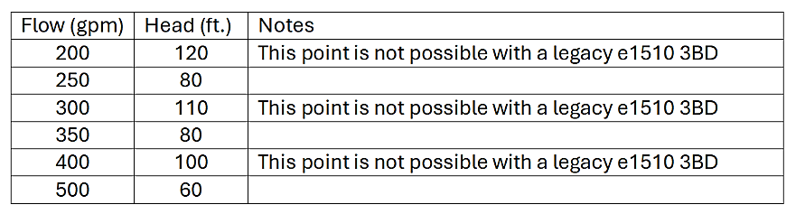
table 1
As mentioned above, the operating voltage must be specified when ordering a smart pump, as the pump is supplied with a motor and an integrated controller. Unlike induction motors, permanent magnet motors are designed for operation within a specific voltage range (380-480VAC or 200–240VAC). They cannot be rewired to operate at a different voltage range.
Stay tuned to the JMP Academy blog for a deeper dive into smart pump selection later this year.
