

Three Types of Curve Control for Variable Speed Pumping Systems
/By Chad Edmondson
We’ve been talking about variable speed control since September 11, 2017, beginning with this blog ASHRAE 90.1-2010/2013: Impact on Variable Speed Pump Control in Chilled Water Systems. Throughout our coverage of this topic, we have introduced and re-introduced the concepts of “Curve Control” and “Area Control” as variable speed pumping control strategies, each time digging a little bit deeper. Today we are going to take an all-inclusive look at Curve Control, because we feel like the concept is often misunderstood and many times exclusively associated with “Sensorless Control.”
SPOILER ALERT: Curve control doesn’t have to be sensorless!
We typically see three different types of variable speed curve control strategies used, and only one of them is technically sensorless. They are as follows:
- Sensorless Curve Control
- Pump Head Curve Control
- Full System Flow Curve Control
(Note that this is terminology that we at JMP use to categorize these strategies. Others may refer to them differently, but the concepts remain the same.)
So, let’s look at each of these one by one….
Sensorless Curve Control. Any time curve control is used as a strategy to control variable speed pumps, the goal is to keep the pump operating on the buildings control curve established by the design engineer. For every point of flow on the control curve, there is a unique speed. So if you know one you can determine the other.
In sensorless curve control, the controller calculates the system flow based on the kW, rpm and, of course, the impeller size of the pump. Using this estimation of flow, the pump controller can then adjust the RPM of the pump so that it stays on the control curve. We are basically using the variable speed drive and the pump as a flow meter; but instead of physically measuring flow we are calculating an estimated flow.
Not every pump is suited for sensorless control. Ideally, the pump curve for the pump you choose will be shaped so that the horsepower line intersects with the pump curve at one easily defined point like this:


On the other hand, if the pump curve looks like the one below, you are going to have trouble:

Notice that a pump with a 6.25 impeller at 3 horsepower follow approximately the same slope between 310 GPM and 450 GPM; it’s a guessing game what the pump flow would be without an actual flow meter installed in the system. This pump would not be suited for sensorless curve control.
It is also important to know that choosing a sensorless control strategy limits your choices of variable speed drive manufacturers. In sensorless applications the variable speed drive and its control are typically exclusive to the pump manufacturer; this can be a problem if there is a failure.
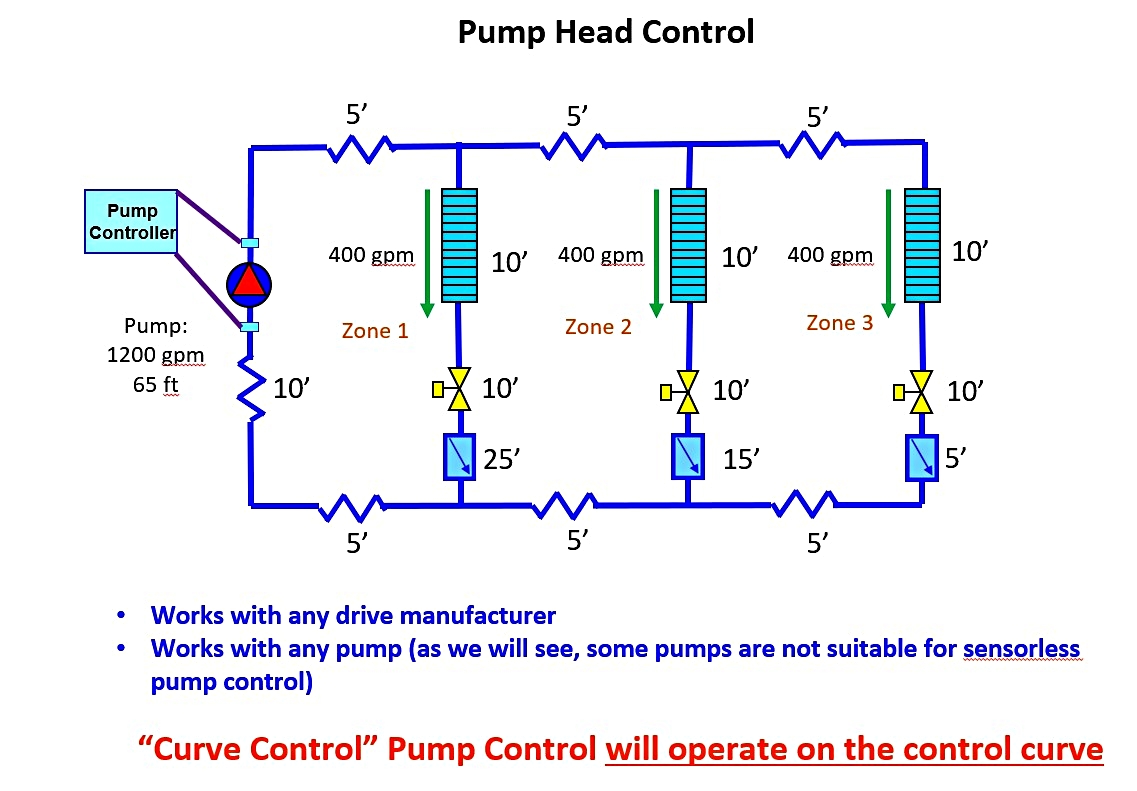
Pump Head Curve Control. Pump head curve control compares the pump head pressure differential to the motor RPM to see where the pump is operating on the pump curve, and then adjust the speed to keep it on the control curve. This method requires a pressure sensor across the inlet and outlet of the pump to measure the pressure differential as shown in the diagram below.
Full System Flow Curve Control. Full system flow curve control works on the same principal as sensorless curve control except we are using a flow meter to read real flow versus an estimated flow. This, of course, provides more accurate pump control. The flow meter is typically located on the discharge of the pump. Once again if we know flow rate and speed we can slow down or speed up the pump as needed to keep it operating on the control curve.

The primary advantage of both full system flow and pump head curve control is that each is compatible with any drive manufacturer or any pump. This is not the case for sensorless curve control. Some pumps, as we saw above, will have curves that make it impossible to accurately estimate flow because the exact operational horsepower and pump curve lines do not intersect at a finely defined point.
Finally, it is important to note that whenever a curve control strategy is in used (regardless of whether it is sensorless or otherwise) most pump manufacturers will default the control head of the pump to a value that is 40% of the design head. For example, if the full design flow requires 100 feet of head, the control head (the required head a zero flow) would be 40 feet.
Why specifically 40%? Because most systems will not meet the following ASHRAE requirement with a control head setpoint greater than 40% of design head:
6.5.4.1 Hydronic Variable Flow Systems. HVAC pumping systems having a total pump system power exceeding 10 HP that include control valves designed to modulate or step open and close at a 50% or less of the design flow rate.
Individual chilled water pumps serving variable flow systems having motors exceeding HP shall have controls and/or devices (such as variable speed control) that will result in pump motor demand of no more than 30% of design wattage at 50% of design water flow.
To stay below 30% of design wattage at 50% of flow, the engineer will likely have to have a control head set at no greater than 40% of design head. Because manufacturers default to 40%, it is recommended that during commissioning the specific control head needed for your system be programmed into the pump controller so as not to waste energy.
