
Manual Versus Automatic Balance in a Variable Speed Pump Control System
/By Chad Edmondson
We’ve talked about manual versus automatic balancing methods and we’ve talked about curve control versus area control. Now it’s time to consider the balance valve type impact on the pump control area.
Let’s start this conversation with a question: How much pump head do you need in a manually balanced system at part load?
The short answer is, it depends. To illustrate what we mean, consider the following proportionally and manually balanced system with a design flow of 1000 GPM and 84 feet of head. We are using differential pressure area pump control with a control head of 20 ft.
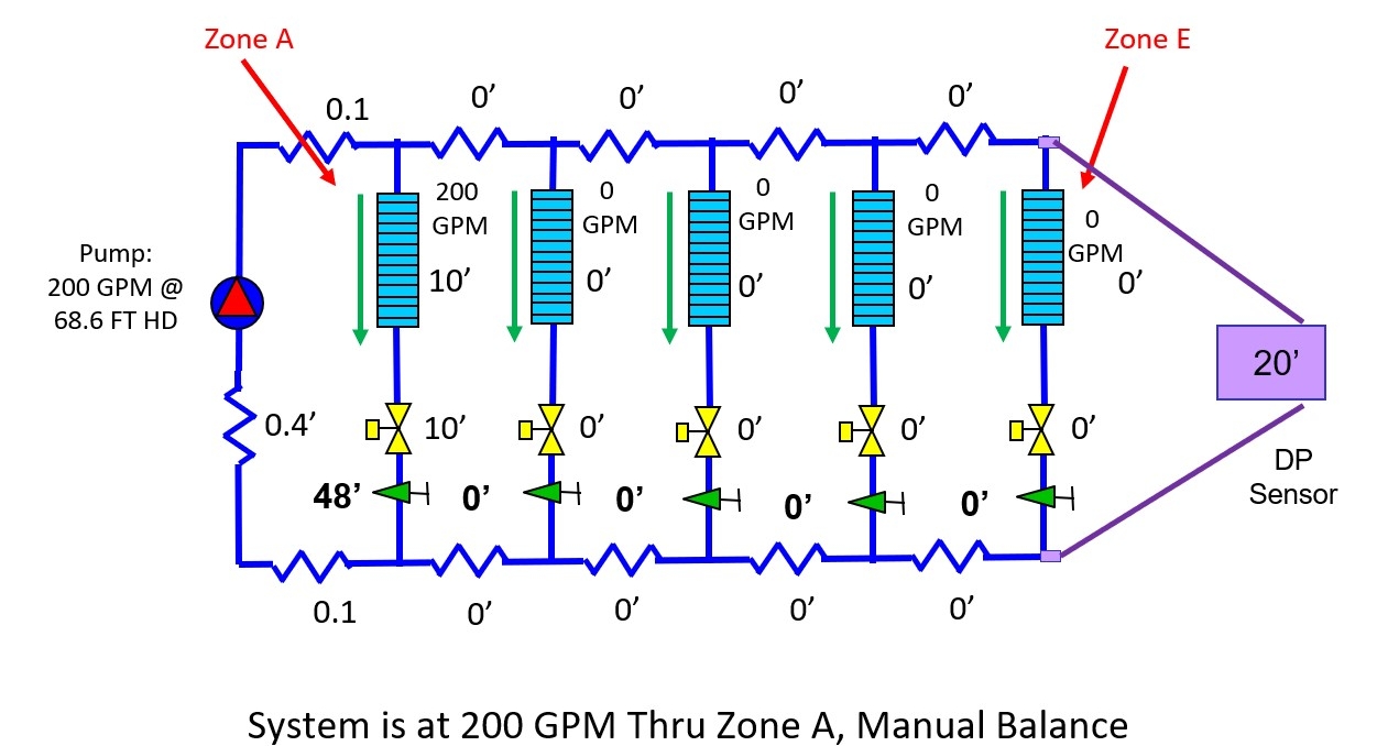
Balancing is easy enough at full load with 200 GPM going to all 5 zones as we can see with the following diagram:

But what happens if system demand drops from 1000 GPM to 200 GPM? It’s kind of a trick question because we don’t know where the load is. It could be in Zone A or it could be in Zone E. It could be split between two or more zones. In a typical HVAC system where the zone loads are never the same, it’s anybody’s guess where the load is. That’s a real problem since head loss varies depending on the location of the load and the pressure losses through the branch pipe.
To better illustrate this dilemma and keep it simple, let’s pretend that the 200 GPM load is all in Zone A. If that’s the case our pressure drop adds up to approximately 69 feet. That’s how much pump head we need to establish full flow through Zone A. Depending on the type of pump control we have we will most likely experience a flow miss in the above system if we are using manual balance valves.
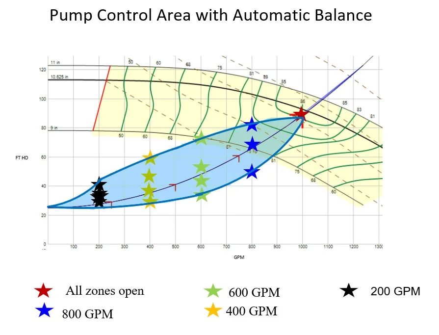
The black stars on the curve below represent the head requirements for the system at 200 GPM for the multiple zones. If we repeat this for other flow points we can plot the pump control area for the system:

So, pressure drop varies quite a bit depending on where the flow happens to be. For example, at 200 GPM, the actual pressure drop could exist anywhere along the vertical line of black stars. This represents a large pump control area which increases the potential for flow misses.
What Happens When Automatic or Pressure Independent Balancing Valves Are Used?
Now let’s look at the same system utilizing automatic balance valves or pressure independent control valves. If this is the case, then our pressure drop adds up to only approximately 26 feet to give us full flow thru Zone A.

We can then calculate the control area for the same system except with automatic balance valves. Note our control head setpoint is now 25 FT to take into account the pressure drop needed for the automatic balancing valve.
Because automatic balancing valves can unload pressure drop, we are able to decrease the amount of pump head needed to fully flow Zone A at part load when compared to a manually balanced system. The amount of this decrease depends on the pressure drop in the branch headers. Therefore, a manually balanced system typically has a larger control area than an automatically balanced system—something the engineer must be aware of when designing the system, depending on his type of pump control.
