

Types of Balancing Devices for Systems with Variable Speed Pump Control
/By Chad Edmondson
Today’s flow balancing devices for variable flow pumping systems fall into three main types:
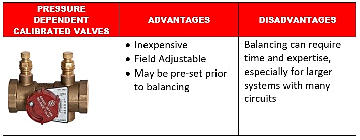
- Pressure Dependent Calibrated Valves
- Pressure Independent Flow Limiting Valves
- Pressure Independent Control Valves
Pressure dependent calibrated valves, commonly referred to as circuit setters, are used for pre-set proportional system balancing. Circuit setters incorporate a ball valve and two pressure ports through which the entering and exiting pressures can be measured to determine the pressure drop across the valve. A calibrated plate makes it possible to balance and set flow. Circuit setters are field adjustable and may be preset prior to balancing. They are inexpensive and readily available, however getting them properly set up at system start-up can be require time and expertise, depending on the number of circuits.
Pressure independent flow limiting valves have cartridges on the inside that move back and forth in response to system pressure changes. This movement increases or decreases the size of the internal orifice. When the entering pressure is low, the spring-loaded cartridge inside the valve opens, and in doing so allows more flow to pass through the valve despite the low pressure. As entering pressure increases, the pressure acts on the spring, compressing it and reducing the orifice size so that flow is limited through the valve. In either case, flow is quickly stabilized despite system pressure fluctuations – as long as the pressures are within the operating range of the specific valve.

Flow limiting valves are shipped preset from the factory based on the maximum GPM, which saves balancing time at the jobsite. Proper sizing is extremely important for accurate control, because once the system gets out of a specific valve’s operating differential pressure control range, the valve becomes a fixed orifice device, and you’re no longer limiting the flow.

Some flow limiters have dials that allow them to be adjusted for a specific flow once they are installed. This eliminates the time-consuming process of matching up valves to specific floors or equipment, and provides an extra bit of flexibility when it comes to operating flow range.
Finally, there are pressure independent control (PIC) valves, which combine the functionality of a balancing valve, control valve and a differential pressure regulator all into one valve body. We recommend using a valve that maintains its full stroke capability despite any preset maximum flow rate; therefore, the valve maintains full authority under all load conditions.
PIC valves incorporate a spring loaded differential pressure regulator, which constantly adjusts and compensates for fluctuations in system pressure. This internal element responds to pressure changes by moving up or down to maintain a constant flow despite these fluctuations. That is the key benefit of PIC valves - a change in differential pressure does not cause a change in flow!
PIC valves do not merely limit flow; they keep flow at a specific setting depending on the signal to the control valve. This eliminates underflows and overflows through the coil and ensures a much more consistent energy transfer.
The diagram below breaks out the functionality within the PIC, including the balancing, control, and differential pressure regulation:

To understand the operation of the PIC, let’s assume we have installed the device on a coil sized for 900 GPM as shown above. We have 34 PSIG entering the valve and 27 PSIG going out, meaning we have a 7 PSIG differential across the valve. The signal from the BMS is 8 volts to the valve actuator. We have 26 PSIG leaving the valve so the balance portion of the valve is absorbing 1 PSIG.
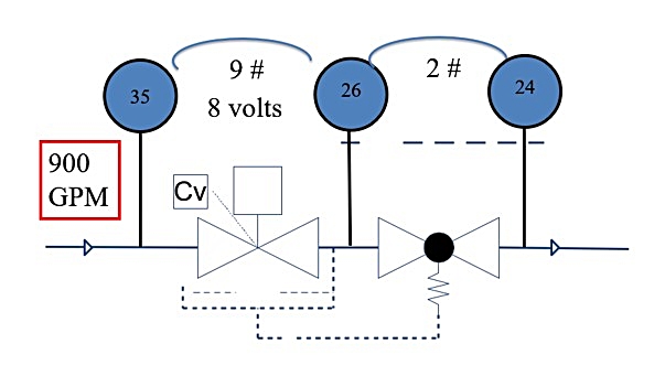
So, what happens if the demand drops in the zone next door, causing pressure to rise and subsequently increasing the entering pressure from 34 to 35? Keep in mind, the demand in the zone shown above has not changed; the control signal is still at 8 volts. However, the variation next door has created an increase in pressure differential across the control valve form 7 PSIG to 9 PSIG.
To keep things right within this zone and maintain proper flow, we need to reestablish a 7 PSIG differential across the control valve. The PIC responds to the current condition by throttling the balance portion of the valve to absorb the additional pressure – in this case increasing the differential from 1 PSIG to 4 PSIG, while also maintaining flow at 900 GPM:

If this gets confusing, think of the PIC as coming complete with a tiny pipefitter who is constantly receiving data from the BMS, as well as pressure and flow information, and swinging into action by throttling the valve as needed.
Only a change in load to a particular zone will result in a change in flow rate through the corresponding PIC valve. All this makes PIC valves the most accurate and efficient choice for variable speed pumping systems.

Up next, we’ll look at how valve types impact the all important control area of a system, which we discussed in an earlier blog.
