
Commercial Sewage Lift Stations Part 5 - System Components
/By Chris Edmondson
Just in case you haven’t gotten the message in this series on designing a commercial sewage lift stations, the design process involves a lot more than selecting a sewage pump or sump pump. The most reliable sewage lift stations are those that are designed and specified as systems and include all of the carefully selected components required from inlet to discharge.
These are the components that should be incorporated in any commercial sewage lift station design:
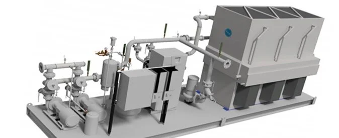
Sewage/Sump Pump & Motor. There are basically 2 choices here – either a submersible pump and motor (more common) or a vertical pump and motor. Vertical pumps have an extended enclosed shaft between a submerged sewage pump or sump pump and a standard vertical motor, which is mounted above the sump cover. Vertical pumps and motors are frequently chosen when there is limited vertical space in the basin. They also offer users the ability to service the motor without having to open the basin and lift the sewage/sump pump out and typically use off-the-shelf type motors. Be careful to make sure you have enough vertical room to remove this type of pump. Submersible pumps and motors are designed to be totally submerged in the liquid within the basin.
Basin (Concrete or Fiberglass). The basin is the container that collects the sewage and houses the pump(s). The engineer must size the basin according to the demands of the job and also choose the best construction material – typically concrete or fiberglass, although basins can be constructed of many other materials.
Valve Box. The valve box contains the on/off valves and check valves for each pump. They are typically located external to the basin so they can be accessed without going into the sump. While this is the more common valve configuration, inline on/off valves and check valves may also be located above sump or sewage pumps without the box but above the basin cover. Engineers should, however, confirm that this is acceptable by local code.
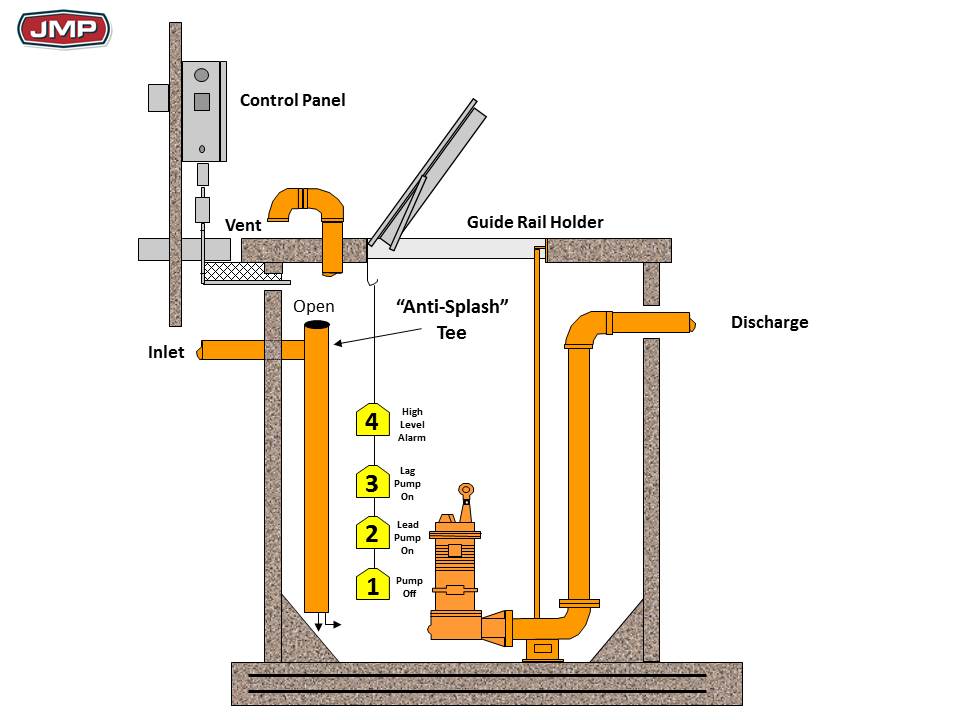
Electric Panel and Level Controls. The pump controls and as well as the float level controls should be included in drawings. The control enclosure should be the proper NEMA assembly, according to the location environment (indoor, outdoor, corrosive, etc.) The exact location of the float controls should also be explicitly noted in the plans.
Removal System/ Guiderail System. Most local plumbing codes require a removal system for submersible pumps so that it isn’t necessary to service them from inside the pit. These guide rails allow for stable removal of the pumps by chain. At JMP, we urge engineers to specify that stainless steel chains be attached to the pumps for lifting and not galvanized chains, which do not hold up in a sewage environment.
Wet Well Covers. Wet well covers attach to the top of the basin. These covers are available in round, square and rectangular designs and are typically made of fiberglass or steel. The covers, along with their dimensions, should be included in the plans.
Access Frames and Hatches. The hatches are installed on the wet well cover. They serve as the access doors through which the pumps can be removed for inspection. They are typically made of aluminum and are mounted on frames or curbs. Obviously, the hatch needs to be sized large enough for removal of all the submersible equipment in the pit.
Anti-Splash Tee. This is not a requirement, but a veteran’s trick to eliminate unnecessary servicing of the floats. By installing a tee at the inlet to the basin and attaching a pipe that extends into the depths of the basin, the sewage is guided directly to the bottom of the sump. This eliminates any surface splashing caused by solids as they drop into the pit. Splashing can cause the floats to clog and necessitate servicing. Anti-splash tees are a simple and inexpensive way to eliminate this problem and a worthwhile inclusion in the plans.
Vent. The International Plumbing Code (IPC) requires that a sump pit to be vented. Sump vent sizes shall be determined in accordance with Table 906.5.1 but shall in no case be sized less than 1¼ inches.
Ideally all of the above components should be noted in the plans and purchased from the same vendor if possible. This assures proper system operation and minimizes the chances for installation error.
For more information, check out JMP’s webinar on designing sump and sewage systems.
