

Parallel Pumping in Condenser Applications: Part 3 of 5
/By Chad Edmondson (JMP) and Norman Hall (RLD)
Chilled water condensers normally operate as constant flow devices and the pumps serving them are constant speed. Why would you ever use a variable speed drive for a pump in this application? This week we show you a couple of reasons.
In Part 2 of this series we used a variable speed drive with contact closure points to operate at full speed when all condensers are active and reduced speed when only one or two of the condensers are operating. What if we add a pressure differential sensor across the system? Is there any advantage to incorporating automation?
The example used in Part 2 is 800 GPM per condenser for a total of 1600 GPM with the third condenser as standby. The tower elevation or lift is 10 feet, the condensers are equipped with two-way balance valves that have 20 feet of pressure drop, and the common piping with any safety factor has 30 feet of pressure drop.
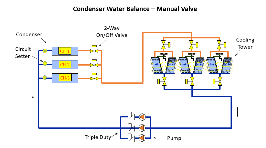
The two pumps selected were in parallel, each with a capacity of 800 GPM at 50 feet head. A third pump was selected for standby. In parallel pumping, the single pump operation is at the intersection of the single pump curve and the system curve. However, in Part 2 we demonstrated how the flow of one pump in parallel operation with the condenser might exceed the 800 GPM design. In our example, the flow rate was high enough to cause velocity issues in the condenser.

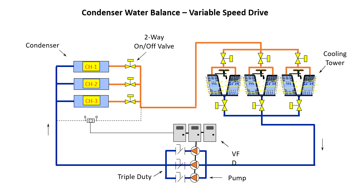
Assuming that each condenser is identical, what might we gain by adding variable speed drives, (VFDs) to the pumps and a differential pressure (DP) sensor across the headers?
The representation below shows the DP sensor across the condenser header. Since the condensers are all equal flow, the two way valves are on-off, and the balance valves adjust for piping differences, a single sensor may be used with a single set point.
Part 2 of this series addressed the advantages of using a VFD to avoid the excessive flow rate through the condensers. There is an additional advantage to using an automatic DP control which may be a tremendous benefit to your end user client, which has to do with the fact that virtually all pumps are over-headed. We add a safety factor to pump head calculations. We may also add extra pump head to offset some of the plugging that occurs in cooling tower strainers. We may even use a lower roughness coefficient like C=100 in the Hazen-Williams formula to account for scaling as the pipe ages.
We know strainers will foul in an open system and the end user is faced with the job of checking the strainers often. If your design uses a DP sensor, there is little question that the operation at 100% design flow will result in pumps operating at less than the nameplate RPM and that will save operating costs. Additionally, as the strainers clog up, the speed will increase to maintain the DP setting at the condensers. The more clogging, the higher the pump will speed up. You could set a building management system alarm if the pumps ever get to full speed or a speed of your choice. That alarm would indicate it is time to clean the strainers out, which would in turn save valuable maintenance time spent checking strainers. Consider what that might be worth to your end user!
One final note: Using variable frequency drives in condenser water pumping systems is not a free pass to grossly oversize pump head. We highly recommend that a detailed pump head analysis be documented with a conservative value included to accommodate strainer fouling and aging pipe.
Next week, we'll look at the use of unequal condensers in this application
