

Hydronic Balancing Part 7: When to Trim the Pump Impeller
/By Chad Edmondson
Balancing isn’t just about adjusting valves. Sometimes (very often in fact) it is about evaluating the performance of the pump(s) under real world operating conditions.
Remember what ASHRAE 90.1 has to say about Hydronic System Balancing:
“Hydronic systems shall be proportionately balanced in a manner to first minimizethrottling losses; then the pump impeller shall be trimmed or pump speed shall be adjusted to meet design flow conditions.”
But how does one determine if a pump impeller on an installed pump needs to be trimmed?
First, it’s important to understand that an installed system almost never matches what is in the original drawings. Pumps may be oversized and head losses may be different from what was originally calculated by the system designer, depending on how the contractor piped the system. Therefore it is important to determine where a pump is operating based on the actual system curve, not the theoretical curve.
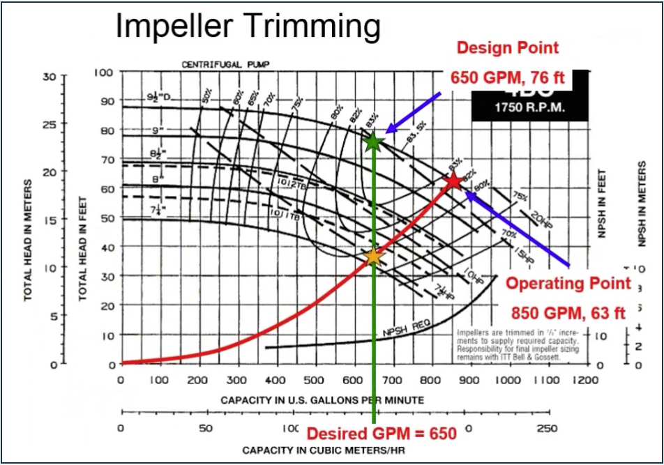
To better understand this, let’s say we have a single pump system with a design point of 650 GPM at 76 ft. of head.

In other words, this pump has been selected to deliver 650 GPM to the critical circuit. The design engineer did his system head loss calculations and determined that we needed exactly 76 ft. of head to pump this system. Based on these criteria, he selected the following pump:

However, once the pump is installed the owner reports excessive noise in the piping. This is our first clue that actual operating conditions are not quite as anticipated, so a little detective work is in order.
Out of Balance
First, we must determine how much head and flow the installed pump is generating. Using the same pressure gauge, we take reading at the pump suction and discharge and discover that the pump is generating 65 ft. of head. Right away we notice that something is not quite right. This pump was picked, after all, to deliver 76 feet of head. We consult pump curve and see that the corresponding flow for 65 Ft. of head is 850 GPM, not the 650 GPM design flow. We’re over-pumping the system and that has resulted not only excessive noise, but also wasted energy.
Our system is not balanced. We are generating more flow than we need, and as a result we are out of compliance with ASHRAE 90.1 and we’re wasting energy.

Throttle, Trim or Replace?
We could put a Band-Aid on the problem and simply throttle the pump back so that reduce flow back to 650 GPM, but ASHRAE says we’re not supposed to do that either. Remember, we want to minimize throttling because throttling wastes energy – and money. A more appropriate solution is trimming the impeller or perhaps even replacing the pump.
Continuing with our example, we now know our pump and our system are not exactly a match made in heaven. Sure – we can throttle the pump back and even save the owner a little money over what he or she is paying now, but the real question is how much more money could we save if the pump was a better match for the installed system.
With a triple duty valve, we can force the system back to its intended operating point on the curve. In this case, that would reduce our operating cost (based on .06 kW) from the previous annual operating cost (AOC) of $8000.00 to $7400.00. Seems like a win, but is it?
What if instead we make our adjustment to the pump instead of artificially adding more resistance to the system? We can determine the outcome of this solution simply by creating a system curve for the system that we actually have rather than what was predicted/intended by the design engineer. To do that we use our known operating points of 850 GPM at 63 ft. of head and our System Syzer to plot the points of our actual system curve. (You can review how to plot a system curve here.)

Using these points, we can plot a new system curve (our real life system curve) onto the pump curve. Keeping in mind that we only need 650 GPM to serve this system, we simply draw a vertical line on the pump curve upwards from the 650 GPM to see where it crosses with our system curve.
As you can see in pump curve shown below, the intersection occurs just slightly above the curve for a 7-¼” impeller – or approximately 7 ½ inches, a far better match for our system than the 9-½” impeller we currently have.
Notice also the drop horsepower from 17 bhp (how the system was originally running – no trim, no throttle) all the way down to 7 ½”HP. Now our annual operating costs are SIGNIFICANTLY less -- $3600.00 versus $8000.00. That’s a far greater improvement over the $600.00 we would save simply by throttling valve.
If our system head just was slightly less, the intersection point with the system curve might occur below this particular pump, in which case we would probably want to replace the whole pump.
Finally, there is one other solution. We could install a variable speed drive on the pump to slow it down – thus changing its performance curve. In this case, however, a trim is all we need to balance the pump with the system, and meet ASHRAE 90.1.
