
Hydronic Balancing Part 6: What Kind of Pumping System Do You Have?
/By Chad Edmondson
Balancing contractors and facility operators would have a much easier time balancing a hydronic system if they were present during the system design process. Unfortunately that is rarely the case so there is usually a certain amount of detective work that comes with balancing. The biggest part of that is getting a handle on the overall pumping system. You can’t effectively balance a system without understanding the overall flow dynamic. For that reason, we always recommend making a basic sketch of the system before the balancing process begins.
Pumping systems typically fall into one of five types, which are all noted below. Once you know what the system looks like in a single snap shot, you are in a far better position to balance it. What you’ll find is that the system is likely to bear a striking resemblance to one of Figures 1 through 5.
Figure 1 shows a basic primary-secondary pumping system, with constant flow through the chillers and a separate secondary pump serving the system load. In this system the primary flow is isolated from the secondary flow by virtue of the common (decoupler) pipe shown in green between the two loops. The chillers will be individually balanced for a constant design flow whereas the building flow will vary based on load.
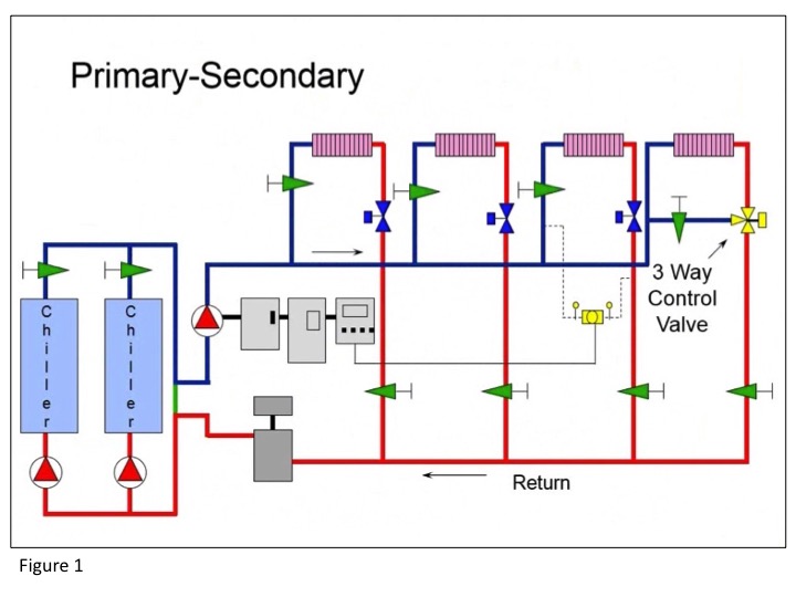
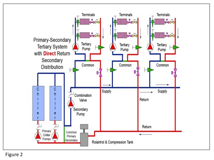
Figure 2 shows a slightly more complex pumping arrangement known as Primary-Secondary Tertiary. The good news about this type of design is that it can be easy to balance, as each building/load has its own pump with a decoupler pipe located between the secondary loop and each of the tertiary loops. This means that changes in one zone will not affect changes in another so balancing becomes less complex. This type of system is also easy to add on to in the future.
You might determine that you have a system like the one shown in Figure 3 where there is a single zone remotely located from the others. Note that Zones A and B are pumped by the same pump, while Zone C has its own dedicated pump. Each individual pump will have to be balanced and a 2 way valve added to the Zone C return line.

Figure 4 shows a Primary-Secondary Zone pumping arrangement where, although there are two distinct loops and only one common pipe, we have separate pumps serving each zone. This type of design keeps horsepower down, but adds some additional control complexity, as each zone (pump) must be balanced. Also, since the pumps are in parallel, their performance curves must be compatible.

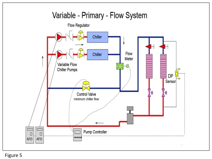
Figure 5 shows a system without any secondary or zone pumps. All of the flow is established by the primary pumps, which vary flow through the chillers according to system demand. A motorized control valve is needed to maintain a minimum flow through the chillers. If designed correctly, this type of system not only has lower installed cost, but also lower operating cost. Balancing however can be difficult as there are no common pipes to isolate flow between the various zones. That’s why pressure independent control valves are often seen in variable primary applications.
In any of the above cases a quick sketch of the pumping system will give the balancing contractor or facility operator the “big picture” perspective that is needed when it comes to balancing.
