
How To Size A Hydropneumatic Tank in A Pressure Booster System
/By Chris Edmondson
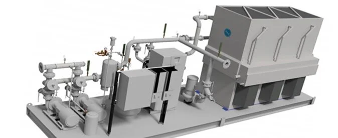
Properly sized hydropneumatic tanks are a non-negotiable element in a domestic water pressure booster system--including variable speed systems. Without a hydropneumatic tank, pumps will short cycle on and off during no flow periods. Even a leaky faucet can cause pumps to operate unnecessarily without this pressurized reserve of water.
As important as these tanks are in a system, it is equally important that they be sized correctly. Sizing is dependent on two factors:
(1) The length of time the designer theorizes that the booster pumps should remain off in a no-flow condition. It is recommended that the pumps stay off between 15 to 30 minutes (depending on the type of building) during periods of low demand to save energy and prevent short cycling. Note that a hospital will typically need a larger tank in order for the booster pumps to remain off for the same amount of time as an apartment building where low usage periods are very consistent.
(2) The tank location in relation to the pressure booster pumps. Tanks that are placed on the roof or at the high point in the system can typically afford to be smaller than those installed at the discharge of the pressure booster.
With that in mind, an engineer can quickly determine the correct size tank for a given application by consulting a few charts and doing some simple math.
Six Steps to a Properly Sized Tank!
Let’s say you have an apartment booster system designed to deliver a maximum of 124 GPM. There is a minimum street pressure of 40 PSIG, and the booster system itself is designed to generate 58 PSIG of pressure for a total maximum pressure of 98 PSIG.
Based on this scenario, these are the steps you would take to determine the proper size hydropneumatic tank:
Step 1. Determine what type of differential you want between the point that the booster system cuts off (98 PSIG) and the time it cuts back on again. For the purpose of this example, we will assume a 10 PSIG differential, so the pump would cut back on when system pressure drops to 88 PSIG.
Step 2. Based on the type of facility, decide how long you would like pumps to stay off during a period of no flow. In our apartment example, let’s say that time period is 15 minutes.

Step 3. Determine the Acceptance Volume for the building type (apartment) and total GPM (124) by consulting an Acceptance Volume chart (Table 1). Based on our example, the Acceptance Volume we need is approximately 19 GPM. However, this chart is based on a 30-minute shutdown instead of a 15-minute shutdown. So we divide 19 gallons by two, giving us a 9.5-gallon Acceptance Volume.

Step 4. Determine your Draw Down Coefficient by finding the initial pressure and final pressure on the Hydropneumatic Tank Draw Down chart in Table 2. In our example, the initial pressure is 88 PSIG and the final pressure is 98 PSIG so the drawdown coefficient is approximately .087.
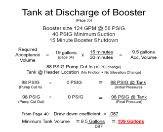
Step 5. Determine the minimum tank volume by dividing the acceptance volume by the Draw Down Coefficient. (See Table 3 for the equation.) Note that we have adjusted for a 15-minute shutdown instead of a 30-minute shutdown in our equation.
Step 6. Determine the minimum tank volume needed by dividing the Acceptance Volume (9.5-gallons) by the Draw Down Coefficient (.087). This gives us our required tank size of 109-gallons.
It is important to remember that the above example is based on the premise that the hydro-pneumatic tank is located at the same level as the booster system. If, on the other hand, the tank were to be located at the top of the system instead the engineer would need to subtract the elevation loses from the initial pressure and the final pressure in order to arrive at the correct Draw Down Coefficient. The calculations remain the same, but this change values will result in a much smaller tank.
Don’t Forget to Pre-charge!
Hydro-pneumatic tanks are shipped from the manufacturer pre-charged to a pressure level that is typically well below what the pre-charge should be at operation. Therefore the engineer should specify the appropriate pre-charge on the drawings.
Table 1
Table 3
