

Cooling Tower and Condenser Water Design Part 1: The Refrigeration Cycle
/By Chad Edmondson
Cooling towers are simple mechanisms. Their operation is based on the natural occurrence of evaporative cooling – something most of us have experienced daily since the first time we got wet and felt a chill. But despite their simplicity, cooling towers play a crucial role in operational efficiency of the entire chilled water system. Not only are they the exit point for all those BTUs in a building that the chilled water system is working so hard to absorb and eliminate, their operation has the potential to significantly reduce the amount kWs going to the biggest energy hog in our system—the chiller.
To appreciate the role that cooling towers play, it’s important to take time to understand the refrigeration process in a chilled water system.
Figure 1
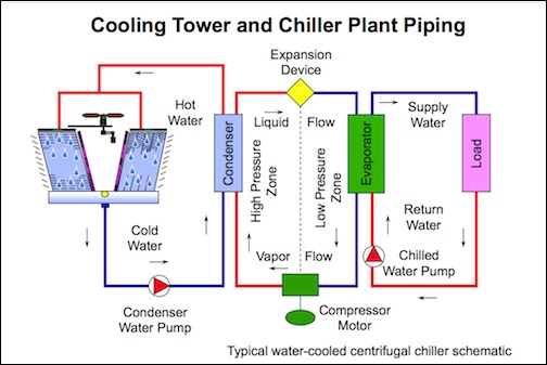
It’s best to begin by thinking about the chilled water system in 3 parts or stages: (1) the condenser water side (2) the evaporator side and (3) the load side. (See Figure 1)
Each of these stages overlaps via some form of heat transfer, ultimately taking the heat from the building and releasing it to the atmosphere using sequential media. In the middle of all of this is the refrigeration cycle.
Refrigeration Cycle
So what happens in the refrigeration cycle?
Basically, the refrigeration cycle is responsible for transferring the heat absorbed by the return chilled water (coming back from the building) and transferring it to the condenser water which circulates to the cooling tower where it releases the heat to the atmosphere. To better understand this, let’s start at the bottom of Figure 1, at the compressor motor.
Note that most chillers are packaged with all of the following components: compressor, condenser, expansion valve, and evaporator. Each of these components is shown in Figure 1. The refrigerant entering the compressor carries with it the BTUs transferred to it from the chilled water loop. As it enters the compressor this refrigerant is in a low pressure/low temperature gaseous state. The compressor “pumps up” the refrigerant into a high pressure/high temperature state, since temperature increases with pressure of any given refrigerant.
This hot gas passes through condenser, where it is cooled and condensed into a liquid, giving up its BTUS via heat exchange with the cooling tower loop. At this point, the refrigerant is in the form of a high pressure/high temperature liquid.
Next stop is the expansion device which reduces the pressure of the liquid refrigerant and consequently cools it to a cold liquid state.
When the cold liquid refrigerant reaches the evaporator (the interface between the return chilled water and the refrigerant loop) it absorbs the heat from the return water, which occurs because at this point the refrigerant temperature is lower than that of the return water. As the refrigerant heats back up, it evaporates into a low-pressure gas. And the cycle begins all over again.
How The Cooling Tower Impacts the Efficiency of Refrigeration Cycle
Given this cycle, it follows that the lower the condenser water temperature (that which is circulating to the cooling towers) is, the less work the compressor has to do. THIS helps keep the operational cost of our chiller down. Specifically, for every pound of water we are able to evaporate in the cooling tower, we absorb another 1000 btus from our building. THAT’S why the efficiency of the cooling tower is so vital to the efficiency of the overall chilled water system.
Next up – how cooling towers operate. (Spoiler – it’s a lot easier than what you just learned!)
For more information about cooling tower and condenser water design, as well as many other hydronic HVAC topics, be sure to check out our online training video series!
