
Parallel Pumping with Optimized Impeller Pumps Part 1: Essential Fundamentals
/By Mark Bingham
Our last series taught us that pumps with untrimmed impellers and variable frequency drives (i.e., optimized impeller pumps) can often exceed design head and flows without penalty. Now, we're really going to blow your mind. Did you know it’s possible to satisfy up to 90% of a design heating or cooling load with just one parallel pump sized at 50% of design flow? In other words, an engineer may be able to provide nearly 100% redundancy for his client with much smaller pumps. That's pretty major, considering the commonality of parallel pump design.
In this short series, we'll discuss how to make the most of optimized impeller pumps in a parallel arrangement.
Parallel Pumping and Redundancy
We begin our discussion with a review of parallel pumping fundamentals.
Most hydronic systems for HVAC include some degree of backup in case a pump fails. Mission-critical installations, like data centers and some medical facilities, require 100% pumping redundancy, also known as N + 1 redundancy. N+1 redundancy requires a standby pump with the same capacity as the normally operating pump.
Most HVAC installations, however, don’t require this level of redundancy. Instead, they typically rely on a parallel pumping arrangement where either pump can provide around 75% of the full flow requirement. While 75% flow is not fully redundant, it is often sufficient to provide 90% of the design heating or cooling requirement. But does the client really need two pumps, each selected for 75% capacity, to ensure ample redundancy? What if there was a way to achieve this same level of coverage with two parallel pumps, each sized for 50% of the design load?
Creating and Evaluating System Curves
Let’s consider what happens to the system curve as flow changes. We can plot a system curve using the second centrifugal machinery affinity law:
h₂ = h₁ x (q₂/q₁)² , where;
h = head (ft, m, …)
q = volumetric flow rate (gpm, m3/hr, l/s…)
This equation tells us that when the flow drops by half, the pressure drop is reduced to one-quarter of the design pressure drop. Likewise, if the flow is doubles, then the pressure drop quadruples.
Plugging different flows into the above equation provides the coordinates to plot a system curve for a given pump. Better yet, we can let a free download of the Bell & Gossett System Syzer® program do all the work for us. (See Hydronic Balancing Part 3: How To Use The System Syzer for more information on System Syzers.)

Figure 1 – System Syzer Pressure Drop/System Curve/Cv Tab
In either case, an engineer can create an estimated system curve like the one shown in Figure 2.

Figure 2 – Typical System Curve
Keep in mind that head estimates are usually higher than what an actual installed system curve reveals. In reality, the system curve will likely shift to the right (Figure 3).

Figure 3 – Estimated and Actual System Curves
An overlay of (constant speed) pump curves onto the system curve shows the flow that one pump will produce when the second pump is not running. In this hypothetical case, a single pump can produce 75% of the maximum design system flow. Consequently, nearby piping accessories, such as the suction diffuser and Triple Duty Valve®, should be selected for the single pump flow rate of approximately 7% of the design flow.
This suggests that, in some cases, two pumps (each sized to 50% of design load) may provide all the necessary redundancy.
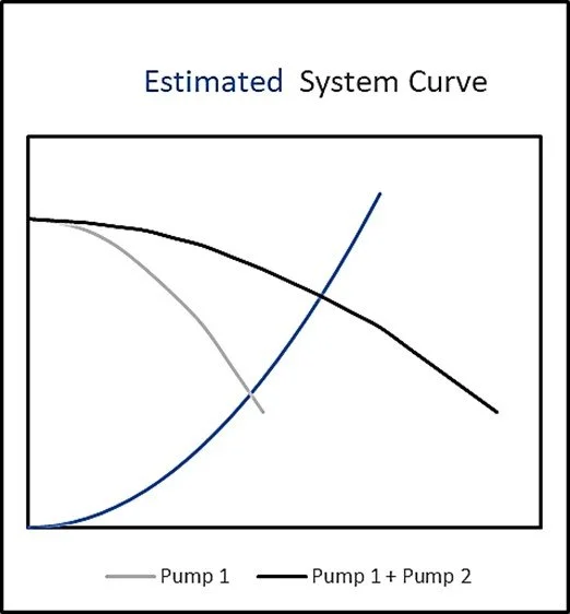
Figure 3 – Estimated and Actual System Curves
What’s Safe and What’s Not
The point of intersection between the single operating pump and the system curve tells us that this pump will still operate safely on its published curve even if the system demands 100% flow. However, as we learned in the previous series, an overestimation of the system head could cause the pump to operate off its curve, leading to cavitation and pump damage. (Figure 5). The only way to remedy this situation is to throttle the pump, thus shifting the system curve to the left. This is a costly solution since this added head will consume energy for the life of the pump. It also may not be permissible under the prevailing energy code, per ASHRAE 90.1 2022 6.7.3.3.3. If throttling is not permissible, the owner must buy a larger pump.
Design engineers can help owners avoid this situation by adhering to ASHRAE 90.1-2022 6.4.2.2, which says, "The pressure drop through each device and pipe segment in the critical circuit at design conditions shall be calculated.”

Figure 5 – Unsatisfactory Operation of a Single Pump in a Parallel Pumping System
It's also crucial to select parallel pumps so that single-pump operation crosses the system curve with room to spare. This can be verified with most pump selection software, which can display a composite system curve and multiple pump curves. Figure 6 is an output from Bell and Gossett’s Systemwize pump selection application showing the system curve, a single pump curve, and a composite curve for operation of both pumps.

Figure 6 – ESP Systemwize Curves for Parallel Pumps
It's helpful to know that if a single pump crosses the system at full speed, it will also intersect at all other speeds. (Figure 7)

Figure 7 – ESP Systemwize Curves for Variable Speed Parallel Pumps
Remember that a single pump operating in a parallel arrangement requires more brake horsepower than the duty point horsepower as the pump runs out its curve. It’s essential to verify the single-pump horsepower requirement or select a non-overloading motor.
Three or More Pumps in Parallel
Finally, systems with high flows may require three or more pumps to operate in parallel. As the number of pumps in parallel increases, it may become impractical or impossible for all pumps to cross the system curve. A judgment call is required in these cases. For example, the engineer may have to decide if two parallel pumps are adequate in case of a single pump failure. This logic assumes the unlikeliness of more than one pump being out of service at any given time. Figure 8 shows this condition in an output from Systemwize.

Figure 8 – Single Pump in Triplex Parallel Pumping System Not Crossing the System Curve
For a more thorough treatment of parallel pumping, see the 2020 ASHRAE Handbook – HVAC Systems and Equipment Handbook, Chapter 44, “Centrifugal Pumps,” the 2023 ASHRAE – HVAC Applications, Chapter 39, “Testing, Adjusting, and Balancing,” and the Bell and Gossett Technical Brochure TEH-1109A, Parallel and Series Pump Application.
Next, we'll examine the impact of reduced flow rates on heat transfer and the implications for parallel pumping design.
