
Hydronic Balancing Part 8: Read & Set Proportional Balance Method
/By Chad Edmondson
What is proportional balancing and why is it a requirement of ASHRAE 90.1 energy code?
The task of proportional balancing is the first step to achieving an energy efficient pumping system. It involves adjusting the system balancing valves to make certain that all zones get proportionate flow under design conditions. Once this task is complete, it gives us the opportunity to trim the fat out of the system for greater efficiency (i.e. by trimming the impeller or implementing variable speed pump control).
The process is straightforward and can be easily illustrated using the following example shown in Figure 1.
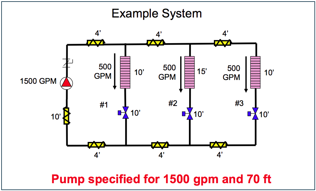
Figure 1 - Over-headed pump on HVAC system.
Here we have a very simplified 3-zone system that has been designed to provide 500 GPM to all three of its zones via a pump specified at 1500 GPM and 70 ft. of head. If you are particularly observant, you may notice that the specified pump is over-headed. If we add up the head losses in the last (critical) circuit, we see that the required theoretical head for this system is 54 ft – not 70 ft. More on that in a bit….
That’s the system on paper, but what happens when we actually turn the pump on?
Anyone in the HVAC business knows that pump and piping systems are rarely (ok, never) installed exactly as they are on the plans. That’s why it is essential to observe and record the actual operating conditions of the installed system and compare it with the design. From there we can begin the process of proportionately balancing the system and adjusting pump speed as needed.
Ready, Set, Balance!
So our simple, 3-zone pumping system is installed and we are ready to get it operating according to ASHRAE 90.1. The steps involved are as follows:.
Step 1. Turn pump on at full design speed, making sure that all valves are full open
Step 2. Locate the critical (most disadvantaged) zone/terminal unit and note the flow through this unit. It is likely to be well below what is required at peak load. Going back to our example, let’s say we turn the system and this is what we find:

Figure 2 - Unbalanced system with pump on and valves wide open.
Clearly this isn’t what we were going for – but remember all the valves are wide open and we’ve yet to balance. We have far too much flow (perhaps even enough to be noisy) going into the first coil, while the most distant coil falls short of the 500 GPM design flow.
Figure 3 shows the actual operating curve (in blue) of our oversized pump versus where it was specified to operate (in green).

Figure 3 - Actual operating curve of oversized pump.
Step 3. Adjust the flow via the circuit setter in Zone 1 so that it is receiving 1/3 of the total flow. Remember, in this particular design, all of the loads are equal, so flow would be apportioned to each in thirds.
(Although Figure 1 didn’t show circuit setters, we know that in the real world each of these zones would have been installed with circuit setters or some other type of flow control device on the return side of the coils.)
Step 4. Adjust the flow in Zone 2 in the same manner as you adjusted Zone 1. Continue to compare this value with the total pump flow, which will drop slightly due to the added resistance of the throttled circuit setters. You want Zone 1 and Zone 2 to be equal in flow AND each to have 1/3 of the total flow. Because you have left the Zone 3 circuit setter wide open, the remaining 1/3 GPM will automatically go to Zone 3.

Figure 4 - Systems is balanced but flow exceeds design flow of 500 GPM to each circuit.
Step 5. At this point your system is proportionately balanced but you still have excess flow so you must throttle the triple duty valve at the pump discharge to reduce flow to the desired 1500 GPM.
Step 6. Having throttled the pump down to 1500 GPM we have confined the excess head in our system to the triple duty valve. With the system running wide open, measure the pressure drop across this valve. This tells us exactly how must surplus we have in the system. In this case it is 16 feet of head.
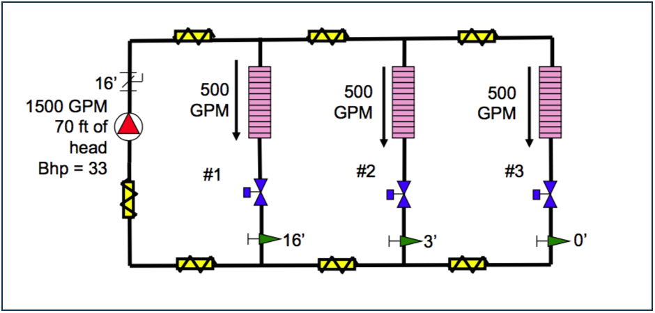
Figure 5 - System with pump throttled to absorb the excess 16 feet of head.
Step 7. Trim the pump impeller or add/adjust a variable speed pump drive to slow the pump down and thus remove the extra 16 feet of head.

Figure 6 - After trimming the impeller (or implementing variable speed pump controls) the system is now proportionately balanced and efficiency maximized.
Note that we are now back to 54 ft. of head, which is exactly what we needed, and the valve at our most critical zone is completely open. All zones are proportionately balanced and we’ve actually dropped our brake horsepower (bhp) to 25 which is a vast improvement over the 36 bhp we started out with. That’s significant when it comes to energy savings and it’s reflective of the kind of energy savings that comes from proportionately balancing the system and making the necessary pump adjustments.
The end result is a system is vastly more efficient and you’ve met an important requirement of ASHRAE 90.1!
