

Domestic Hot Water Recirculation Part 6: Maintaining Temperature Control In Systems with Steam Instantaneous Water Heaters
/By Chad Edmondson
Applying recirculation to domestic hot water systems with steam type instantaneous water heaters requires a little extra attention. The challenge is temperature control. Under very low load conditions, instantaneous water heater supply temperatures may fluctuate rapidly – even dangerously. Here’s why:
During periods of light draw, the heater flow rate may become unstable, fluctuating between a minimal/no load draw recirculation flow rate and that same flow rate plus the draw of a single fixture. That’s what happens when a single hotel guest decides to take a shower at 3AM.
Under these circumstances, the heater control valve/controller senses a sudden drop in supply hot water temperature, as more supply cold water is suddenly forced into the heater. If the sensor only senses temperature and not flow, the message to the valve is simply, “Open wide—we need heat!”
But what happens when you unleash up to 100% of your water heating capacity on a mere 1.5% of your design load? A major rise in water temperature, likely followed by wild fluctuations (hunting) in your supply hot water temperature!
Increase Recirculation Flow By 25%
One way to avoid this situation is to increase the recirculation flow rate through the instantaneous steam heater by 25%. (Consequently you will need to upsize your recirculation pump.) This increase in flow will allow you to use the water storage in the domestic piping to help initiate mixing of warm return water with cold supply water as shown in Figure 1. This will improve the light load temperature stability because with a higher recirculation rate, the controller will see a smaller and slower change in the hot water supply temperature.
Figure 1

How to Avoid Upsizing Recirculation Piping
Just remember that this change in minimum flow rate can result a rather dramatic increase in required pump head unless you increase the size of your return piping—which may or may not be practical depending on the building design.
Let’s say we have an initial 1.9 GPM recirculation flow rate and a friction head loss of 5.2. Head loss varies as the square of flow rate, so if we increase the recirculation flow rate from 1.9 GPM to 25 GPM, suddenly our friction losses increase to 900 ft.!
Required pump heat = (25/1.9)2 x 5.2 = 900 ft.
Clearly, you’d be better off increasing your recirculation pipe size than sizing your recirculation pump for 900 ft. of head!
Another solution to avoid having to install a 2-inch pipe for your entire recirculation loop is to install a bypass valve between the supply pipe and recirculation as shown in Figure 2.
Figure 2
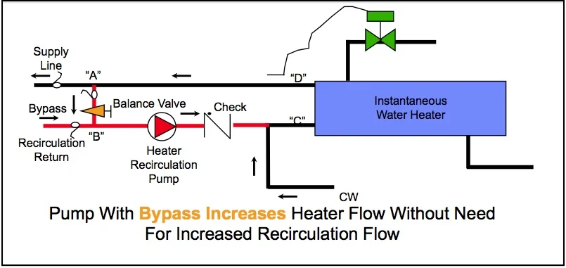
In this case, the pump provides the necessary flow rate through the heater. Flow through the balance valve causes the necessary head difference across A to B to drive the required recirculation flow through the supply piping and back through the recirculation return. That way only a small portion of piping (between the bypass and the water heater) has to be sized up for the increase in flow that is necessary to maintain temperature control.
Stay tuned, and in the meantime check out our previous blogs on this topic and our video:
Domestic Hot Water Recirculation Part 1: What’s The Point?
Domestic Hot Water Recirculation Part 2: Where ASHRAE 90.1 Conflicts with OSHA
Domestic Hot Water Recirculation Part 3: The Role of the Recirculation Pump
Domestic Hot Water Recirculation Part 4: Pump Sizing Example
Domestic Hot Water Recirculation Part 5: Recirculation WITHOUT a Return Line
