

Cooling Tower and Condenser Water Design Part 6: Multiple Cooling Towers and Condenser Piping
/By Chad Edmondson

Larger facilities often have multiple cooling towers serving multiple chillers, enabling them to more closely match demand. Piping such systems can be a challenge, depending on the amount of flexibility desired. Generally speaking, the greater the flexibility in a system (that is, the ability to mix and match pumps, chillers, and/or cooling towers) the more knowledgeable the designer and the operator need to be about how these systems work. Otherwise, you’re putting some pretty expensive equipment at risk.
Option 1: Independent Circuit
The simplest way to design and operate a multiple cooling tower system is the independent circuit approach. This is really no different than installing separate chiller plants. Each chiller has its own pump, its own cooling tower and its own set of pipes. As Figure 1 shows there is no common pipe in an independent circuit design, therefore the operation of one circuit never impacts the operation of the other. This makes control a breeze since there is no balancing between circuits and staging is a simple matter of cutting individual circuits on and off.
However simple, the independent circuit design is not very flexible. Consider the fact that there is no inherent standby for your individual chillers. If one cooling tower fails or needs servicing, you cannot switch its chiller to another cooling tower. That circuit is out of commission until its own private cooling tower is up and running again. Independent circuits are also very costly to install simply because of the extra piping. For that reason alone, independent circuit designs are pretty rare.
Figure 1

Option 2: Header Supply and Return
A more commonly encountered approach to multiple cooling tower designs places a common header in the supply and return piping. As you can see in Figure 2, this piping arrangement has one pump per chiller, but the supply piping from the chillers and to the cooling towers is manifolded together so that a single common pipe supplies the cooling towers and the condenser water pumps. That’s a lot less piping than what you have in Figure 1; it’s also more flexible. At any given time you can switch any one chiller to another cooling tower. Notice the 2-way valves at the top of each cooling tower and also at the bottom. These valves, which operate in concert with one another, open when the cooling tower is in operation, and close when it is not.
By adding butterfly valves between the pumps and the condensers, we can also switch flow from any one pump to any one chiller, giving us pump and condenser stand-by.
Figure 2

This extra flexibility comes with a certain amount of complication—but nothing that a little awareness and precaution can’t overcome. The main concern in a header supply and return design is making sure you don’t overflow any of the chillers during part load conditions. Why is this a potential problem? Because our pumps must be selected, to overcome the friction loss associated with the supply piping at full load conditions. At part load conditions, those friction losses all but disappear in the common pipe. With so little resistance in the piping, it is possible that a high headed pump might run off to the right side of its curve, causing too much flow through the chiller – which can erode the tubes.
Remember, friction losses vary significantly with flow. Double the flow and your friction losses increase by a factor of 4; the inverse is true if you decrease the flow. So, using our example in Figure 2, if we only want to run one cooling tower and one 900 GPM chiller suddenly we are at 1/16 of the full load friction loss. If the pumps chosen for this particular application are high head – say 100 feet of head, then you could have a problem if you haven’t taken the proper precautions to avoid overflowing the chiller. Pump vendors can typically help you select pumps that are in a safe range of 60 to 70 feet of head. If high head pumps can’t be avoided, then flow limiters should be installed at chillers
Option 3: Parallel Pumping
The piping arrangement with the maximum flexibility and standby is parallel pumping and is shown in Figure 3. In this arrangement, the pumps are manifolded together with one single pipe running to all three condensers and one pipe coming back from the cooling towers. The great thing about this configuration is that it allows you to mix and match pumps, condensers, and cooling towers, so you have the maximum amount of stand-by for virtually any situation. However, since all the pump flow is combined into a single common pipe, your risk of overflowing a condenser is even greater than it is in a header supply and return arrangement. For this reason, we strongly recommend installing flow limiters on each condenser to avoid overflowing the chiller during partload conditions. It is also important to include 2-way (on/off) valves on the chillers to prevent flow through the chiller whenever it is off. (A set of 2-way valves should always be included on the cooling tower inlets and outlets, no matter what piping arrangement you choose.)
Figure 3
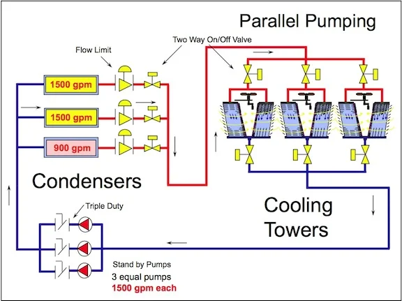
In this arrangement, we also recommend identical pumps – same GPM and same head. It’s not that you couldn’t make it work, say with two 1500 GPM pumps and one 900 GPM pumps, but there’s really little to be gained, and three equal pumps makes control much more simple.
For more information, please view our video series on Cooling tower and Condenser Water Piping Design.
