
Cooling Tower and Condenser Water Design Part 11: Avoiding Common Pitfalls
/By Chad Edmondson
We’ve finally reached the end of our cooling tower series! But before we leave the topic behind we thought it would be a good idea to review some of the most common pitfalls in cooling tower/condenser water design and how to avoid them. We’ve touched on all of these in the previous blogs, but we see them so often and the consequences can be so profound that each bears a final warning. Take care to avoid these scenarios and we promise that everyone (from your equipment suppliers to your chemical treatment specialist) will be much happier.
Low Flow Through Towers
Every cooling tower has a minimum flow requirement, which is defined by the allowable turndown. ASHRAE 90.1-2010 requires a minimum turndown of 50% (i.e. a 3000 GPM tower will be able to operate as low as 1500 GPM.) Older towers however typically do not have such a high turndown range. Many existing cooling towers, such as the towers in our example below, may only have a 35% turndown. This is often where we see low flow problems. Users dip below the minimum flow, begin to experience problems and don’t understand why.
What’s so bad about low flow through cooling towers? As we discussed in Part 5 of this series, low flow leads to dry air disease and the eventual build up of mineral deposits on the cooling tower heat exchange surfaces. The purpose of maintaining the minimum flow is to keep all the interior surfaces of the cooling tower sufficiently wet, which encourages consistent heat transfer by not allowing dry passages in the fill (remember air likes the path of least resistance) and helps avoid mineral build-up. Otherwise your cooling tower fans will work extra hard to overcome a problem that they can only make worse.
Figure 1
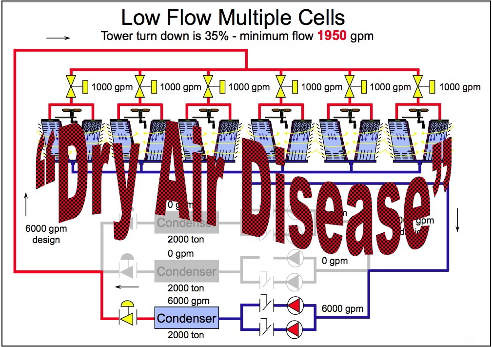
Consider our real life example in Figure 1, which shows all six 3000 GPM cooling towers operating, while only one 6000 GPM condenser is on line. These were older cooling towers with a turndown of only 35%, meaning that they had to maintain at least 1950 GPM to operate properly. With six towers and just one condenser operating, each tower was receiving only 1000 GPM of flow. They were all suffering from dry air disease due to the fact that their flow had dropped far below the minimum threshold of 1950 GPM. A parched cooling tower can never achieve its capacity so even with six cooling towers operating they still couldn’t maintain supply temperatures to just one condenser.
The solution? Valve off the cooling towers so that only three can run during single condenser operation. This gives each tower a flow of 2000 GPM, putting them above the minimum flow requirement.
Towers flooding at Shut-off
Cooling towers are designed not to flood when installed according to manufacturers’ specifications. The sump basin in the bottom of the tower is designed to hold what is called the “pull down volume” of the tower, which includes full volume of water in the fill, the hot deck, and the overhead supply pumping to the tower. However, if the condenser and it’s associated piping is located at an elevation higher than the cooling tower, than the water in all of that equipment will most certainly drain by gravity into the tower, causing it to flood when the pump is turned off as shown in Figure 2.
Figure 2

To avoid this situation you must install a water trap (water leg) between the condenser and the tower to trap any water that might drain from the condenser equipment and piping if the pump is turned off.
Pumping Dry At Start-up
Pumping dry at start-up is an inevitable consequence of the previous pitfall of flooding the tower at shut-off. If you don’t install a water trap to catch the water from the condenser and piping located above your tower, the tower will flood and most of the water will spill out over the sides of the sump as soon as the pump is turned off. Then, when you turn your pump back on, you don’t have enough water in the system and you begin to pump dry, which causes the pump to cavitate. (Figure 3).
Again, the solution is the installation of a water trap.
Figure 3

Air Trap in Suction Piping
Air traps in the suction occur when piping is installed to vertically circumvent some sort of obstruction to a linear piping route – like a road (Figure 4).
Keeping in mind that a cooling tower is open, and that water always takes the path of least resistance, it’s easy to understand why a pump might not pump in this scenario. There is a giant air trap in the vertical and horizontal piping that goes over the road. You can’t blame the pump – as it’s designed to pump water not air.
Figure 4

The only permanent solution to this problem is rerouting the piping beneath the road. In the short term, the only solution is to physically block the cooling dower drain and put water directly into the piping over the road, keeping the cooling tower drain blocked until all of the piping is filled. (A man standing inside the tower on top of a piece of plywood blocking the drain from any backflow into the tower worked for us on one occasion.) This solution will suffice until the pump is turned off, and its prime travels backward and out the cooling tower drain. Again, piping design is key.
These are our most commonly encountered pitfalls. What are yours?
Don’t forget to read Parts 1 thru 10 of this series, and if you prefer video, check out our YouTube series on Cooling tower and Condenser Water Piping Design.
