
Boiler Installation Pitfalls Part 3: How to Size Gas Piping
/Sizing the gas piping for a boiler is pretty simple. The pitfall you most want to avoid is failing to read the Installation and Operation Manual (IOM) for the boiler. It contains most, if not all, of the information you need to correctly size the pipe.
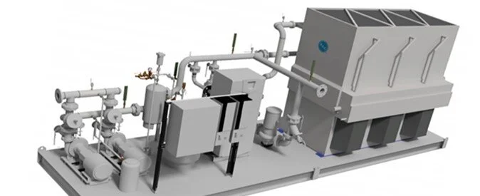
The first step in sizing the gas piping is to determine the length of each pipe run between the gas meter and the boiler, along with the number of tees and elbows. The pressure drop for individual fittings (tees and elbows) is the equivalent of 5 ft of straight pipe, e.g., five elbows would add 25 equivalent feet of pressure drop to the total length of straight pipe. Using the system shown in Figure 1, we can calculate the equivalent feet of the gas pipe as follows:
Straight Pipe:
5 ft + 25 ft + 10 ft + 10 ft + 12 ft = 62 ft of straight pipe
Fittings:
5 ft x 5 ft per fitting = 25 equivalent feet of straight pipe
Total Equivalent Feet:
62 ft + 25 ft = 87 feet

figure 1
Once you have your total feet of equivalent pipe, consult the IOM. There, you will find a natural gas pipe size chart for your specific boiler like this one, which was taken directly from the IOM for the Lochinvar Crest boiler. Charts like these are based on those that can be found in the National Fuel Gas Code.

Keep in mind that while these charts all look basically the same, the values and exact metrics can vary from model to model. The values shown in this particular chart are listed in MBHs (1,000 BTUs per hour).
Since 87 ft is not listed on the top axis, we must choose the next higher value (90 ft) and search the same column for a pipe size that can provide the 1,000,000 BTUs capacity needed for our boiler. Right away we can see that we need a pipe diameter of at least 2 ½ in. In this case, a 2 ½ in pipe is capable of providing 1,480,000 BTUs per hour. The larger pipe sizes will also work and reduce the amount of friction losses but will add unnecessary costs to the project if a larger pipe size is not required.
Most boiler gas pipe sizing charts are based on natural gas with a specific gravity of 0.60 and the recommended pressure drop in inches of water column (w.c.) through the gas piping. In this example, we want to limit the pressure drop in the gas piping to 0.3 in. w.c. These values, which impact the capacities in the body of the chart, will also vary among boiler manufacturers.
Maintain Inlet Gas Pressure
All gas boilers have a maximum and minimum supply pressure. The gas inlet recommended supply pressure can be found in the IOM. The gas pressure for the boiler in our example is tagged with a pressure range between 4 and 14 in. w.c.; however, the IOM for the boiler in our example recommends that we target a supply gas pressure of 7 in. w.c. when the boiler is OFF (“static” pressure).
It is very important to size the gas piping to avoid a sharp pressure drop when the unit starts. When the boiler is in operation, the gas pressure should never drop more than 1 in. below the static pressure reading. We want to sustain at least this much pressure all the way to high fire (dynamic pressure).
Keep in mind that gas valves tend to open and close quickly, resulting in pressure surges. Pressure regulators are required to stabilize the pressure, so the boiler doesn’t fault out on high pressure or drop below the prescribed minimum dynamic (operating) pressure. We recommend selecting 100% lock-up type pressure regulators to prevent pressure spikes from exceeding the maximum operating pressure.
Sizing Gas Pressure Regulators
Gas pressure regulators are typically sized to correspond with the gas inlet to the boiler. Generally speaking, the regulator is normally the same size in diameter as the low-pressure gas inlet connection to the boiler. It should always stay within one pipe size of this connection. The regulators should be installed at least 10 linear feet from the boiler.
Gas pressure regulators also have a pressure drop, which is often unaccounted for in the design. If the regulator is undersized it could cause the pressure drop to be above the 1 in. w.c. that the factory recommends. If our gas piping pressure drop is sized to be 0.3 in. w.c. at full flow then that means our gas regulator pressure drop can be no more than 0.7 in. w.c. to keep us below the 1 in. w.c. maximum loss from the static pressure.
Why an Oversized Gas Regulator Can Be a Good Thing
It is common practice to oversize gas pressure regulators to match the connection size on the boiler to avoid excessive pressure loss. This is one of the few times when oversizing equipment helps more than it hurts. An oversized gas regulator with a high turndown helps reduce pressure spikes (and subsequent high-pressure alarms) when the gas valve closes. This is because the valve seat on a larger regulator with a high turndown is only slightly open at full flow, which allows it to close faster than a smaller regulator with a valve seat that is completely open at full flow.
The IOM and local codes may have additional specifications for the application of gas pressure regulators, so do your homework!
