
Best Practices for Hydronic Systems Part 4: Where to Locate the Pressure Reducing Valve (PRV)
/All closed-loop hydronic systems must have a pressure-reducing valve (PRV). These valves serve two purposes: (1) They reduce the pressure of the city water at system fill to the appropriate system pressure, and (2) They provide make-up water to the system if there is a leak. In either case, you can think of the PRV as a gatekeeper between the system and the city water supply, the location of which is absolutely critical to the functionality of the system and the longevity of the pumps.
The best place to install the PRV is on the suction side of the pump, just like the expansion tank (see Figure 1). This placement ensures that the operation of the pump will not affect the operation of the PRV. Cycling the pump on or off will not affect the pressure at this point.
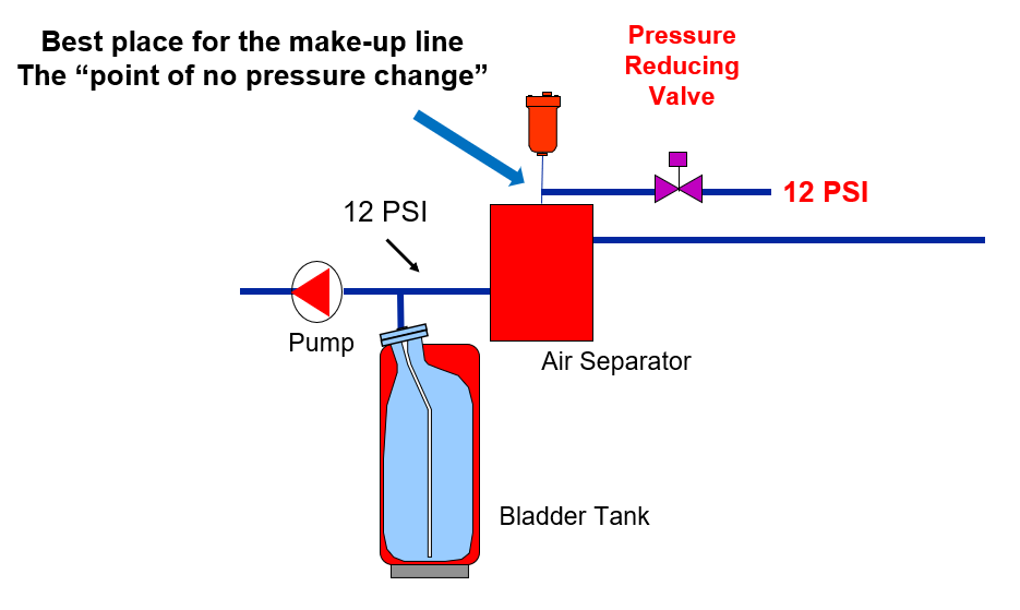
Figure 1
In Figure 1 we see that the PRV is set at 12 PSI. Anytime the pressure drops below 12 PSI the valve will open to add water to the system. Since the valve is installed at the “point of no pressure change” the pressure will not change at this location when the pump comes on.
To understand why this is so important, let’s look at what happens when the PRV is installed on the discharge of the pump (see Figure 2).
When the pump comes on, its discharge pressure increases to 26 PSI. This is the pressure that the downstream side of the PRV is exposed to. This is a problem because the PRV no longer sees only the required fill pressure (12 psi). If a leak occurs in the system, the system pressure will continue to drop until we lose our required system pressurization. At this point, the pump could cavitate, coils could become air bound, and equipment may be damaged.

Figure 2
Monitor Make-up Water!
Keep in mind that PRVs rarely allow the introduction of more water to these systems. Make-up water is typically only needed if there is a system leak or the system has to be drained for some reason. Under typical operating conditions, we want to avoid introducing make-up water to the system because it contains fresh oxygen, which will lead to system corrosion. Even a small amount of air, introduced to the system because of a small, undetected leak, can lead to corrosion. Many times this small amount of flow is not noticed until system corrosion has already started to occur. On the other hand, we have looked inside the casing of 20-year-old pumps and found that they look brand new, simply because they were part of a well-maintained closed system.
One way to mitigate the introduction of make-up air into a closed system is to monitor the quantity of make-up water. In the 2020 Handbook, HVAC Systems and Equipment Chapter 13, ASHRAE states that “Many designers prefer to install automatic make-up valves, which consist of a pressure-regulating valve in the make-up line. However, the quantity of water being made up must be monitored to avoid scaling and oxygen corrosion in the system.” This can be accomplished by installing a flow meter or flow switch on the water make-up and connecting it to an alarm. If there is a small leak, the alarm will notify the owner or operator and the problem can be fixed before corrosion sets in.
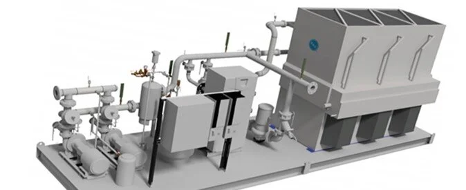
To ensure that the make-up assembly is installed correctly from the beginning we recommend using a packaged make-up assembly (see Figure 3). Not only does this assembly come with a properly-sized PRV, but all of the other components required for a correctly installed make-up, including the relief valve, pressure gauge, PT port, dielectric nipple and shut-off valves. These make-up assemblies can also be supplied with a backflow preventer. Information on HYFAB make-up assemblies can be found here.

Figure 3. A closed-loop hydronic system should contain a pressure reducing valve to provide make-up water to the system and pressurize the system to avoid air or pump cavitation issues.
